
Electrode Potentials & Electrochemical Cells
Apprends en jouant
Réponds à ces questions pour gagner de l'énergie, puis pêche et explore. Sans compte.
Notes de leçon
Separate redox processes to obtain electrical work
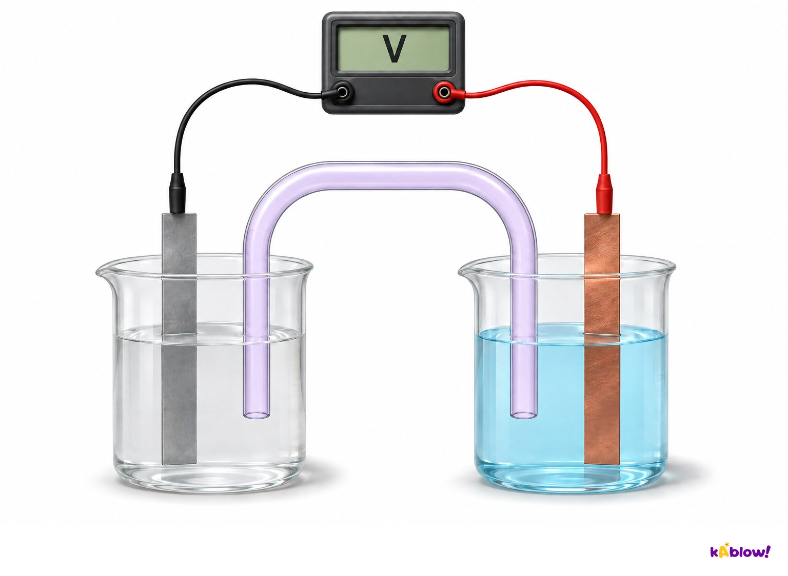
- In a galvanic cell, oxidation and reduction occur at different electrodes. Electrons can pass through an external conductor while ions carry charge through the electrolyte and junction.
- For Zn+Cu²⁺→Zn²⁺+Cu, zinc supplies electrons and copper ions accept them. Separating the half-cells allows the electron transfer to drive a load.
- Emf is the near-open-circuit potential difference, measured in volts or joules per coulomb. A single electrode potential is measured relative to a reference, not as an isolated absolute voltage.
Separate zinc and copper half-cells
Specify the conditions behind E°
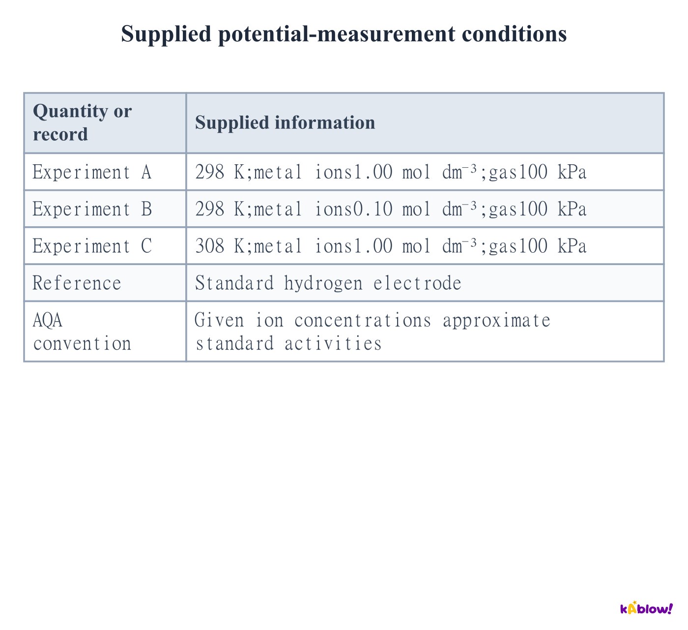
- AQA standard electrode-potential comparisons use298 K, gas pressure100 kPa where relevant, and specified aqueous species at1.00 mol dm⁻³.
- Pure solids or liquids have their specified standard states. More precisely, standard thermodynamic values use activities; concentration is the school-level solution convention.
- Nonstandard temperature, gas pressure or solution composition can change the actual potential. A high-resistance meter minimises current and changes in composition during measurement.
Supplied potential-measurement conditions
Use the standard hydrogen electrode as reference
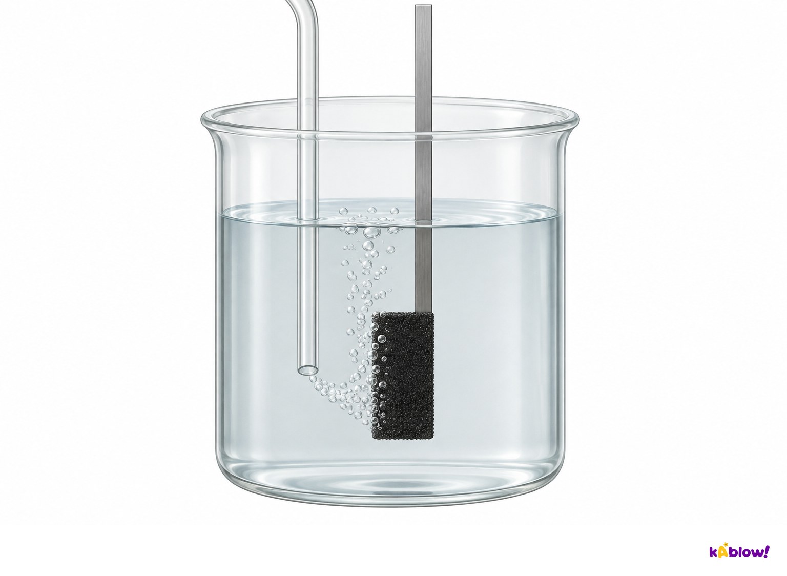
- The hydrogen half-cell uses an inert platinum surface in contact with H₂ gas and aqueous H⁺. The reduction equation is2H⁺+2e⁻⇌H₂.
- At the supplied standard conditions its reference reduction potential is assigned0.00 V by convention. It is not zero because no interfacial process occurs.
- Platinum provides electrical contact and a catalytic surface; it is not consumed in the ideal half-equation. The gas pressure and temperature controls are specified separately from the schematic.
Hydrogen gas contacts a platinum surface
Measure a positive potential against the reference
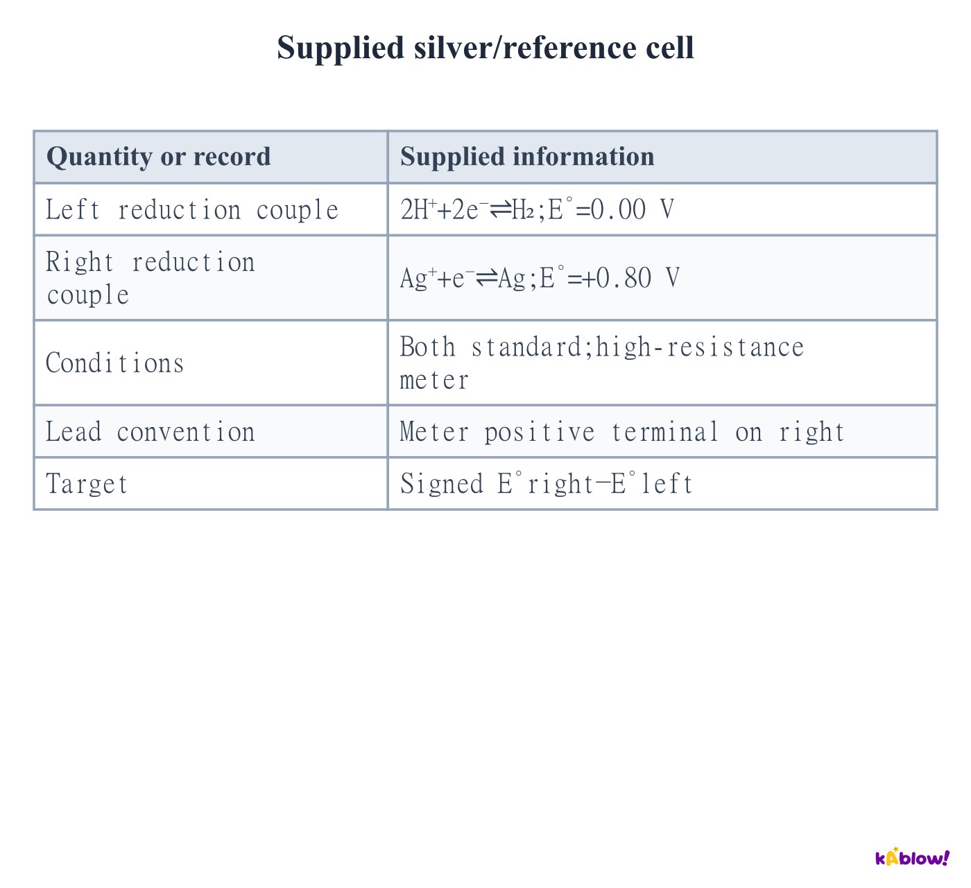
- Write tabulated half-equations as reductions. Compare the standard silver couple with the hydrogen reference using E°diagram=E°right−E°left.
- The supplied hydrogen-left/silver-right diagram has+.80−0.00=+.80 V. During galvanic discharge silver ions are reduced and hydrogen is oxidised.
- The high-resistance measurement draws negligible current. Arrows on an emf schematic describe the direction charge would flow if a load allowed appreciable current.
Supplied silver/reference cell
Interpret a negative signed diagram voltage
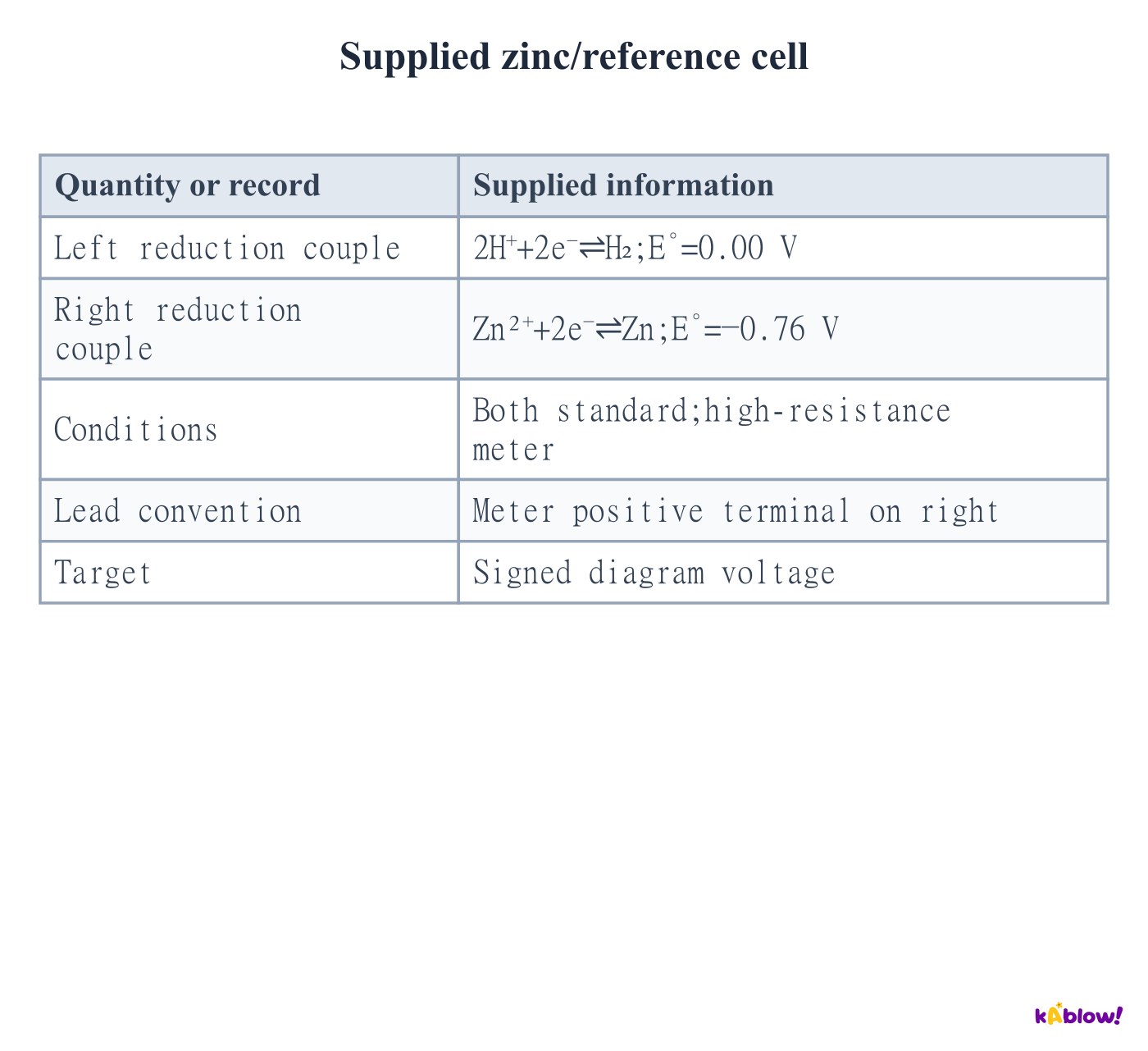
- The supplied hydrogen-left/zinc-right diagram gives−.76−0.00=−.76 V when the meter positive terminal is on the right.
- This negative sign indicates the spontaneous galvanic direction is opposite to reduction at the drawn right-hand electrode. Zinc oxidises and hydrogen ions reduce.
- Reversing the leads or reversing the written diagram reverses the signed reading. Do not always take an absolute value when a question specifies diagram orientation.
Supplied zinc/reference cell
Choose a chemically compatible salt bridge
- A salt bridge supplies a continuous ionic path and helps maintain electrical neutrality. It does not carry electrons between the electrodes.
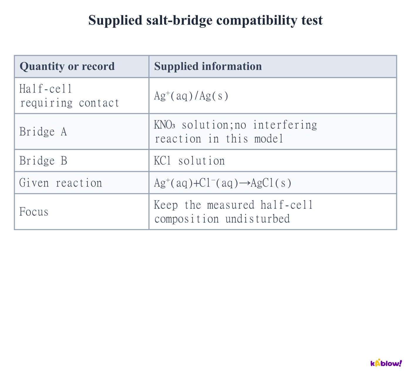
- Its electrolyte must avoid interfering reactions with either half-cell. For an Ag⁺ half-cell, chloride can precipitate AgCl and alter composition.
- Potassium nitrate is a suitable choice in the supplied model. KCl is useful in some cells but is not universally inert; check the actual ions present.
Supplied salt-bridge compatibility test
Track electrons and compensating ion motion
- In the discharging zinc–copper cell, electrons travel externally from zinc to copper. Conventional current in the external conductor is opposite to electron motion.
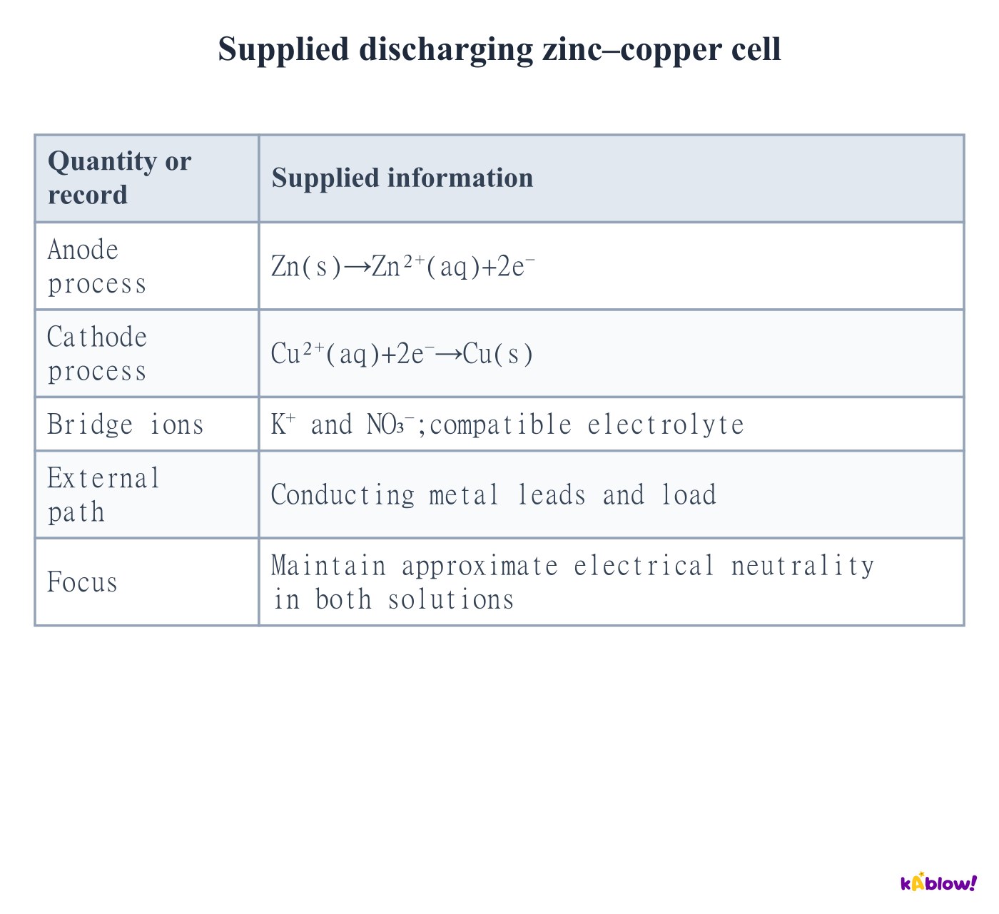
- Zinc oxidation adds Zn²⁺ to its solution; bridge anions migrate toward that half-cell. Copper-ion reduction removes positive charge; bridge cations migrate toward its half-cell.
- Oxidation occurs at the anode and reduction at the cathode. During galvanic discharge the anode is negative and cathode positive; those polarity rules must not be transferred unchanged to forced electrolysis.
Supplied discharging zinc–copper cell
Read cell notation as phases and junctions
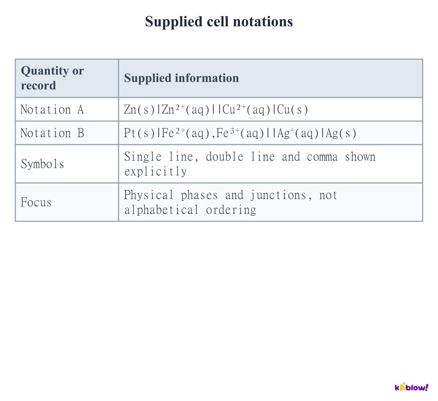
- A single vertical line marks a phase boundary. A double line denotes the junction or salt bridge between half-cells. A comma separates species in the same phase.
- Zn|Zn²⁺||Cu²⁺|Cu lists the two metal/solution boundaries. An ion/ion half-cell can use inert Pt and list Fe²⁺,Fe³⁺ together in one aqueous phase.
- Do not apply a universal rule that the highest oxidation state must be next to the junction. Write the chemically relevant phases and then use the signed right-minus-left convention.
Supplied cell notations
Keep cell orientation and voltage sign consistent
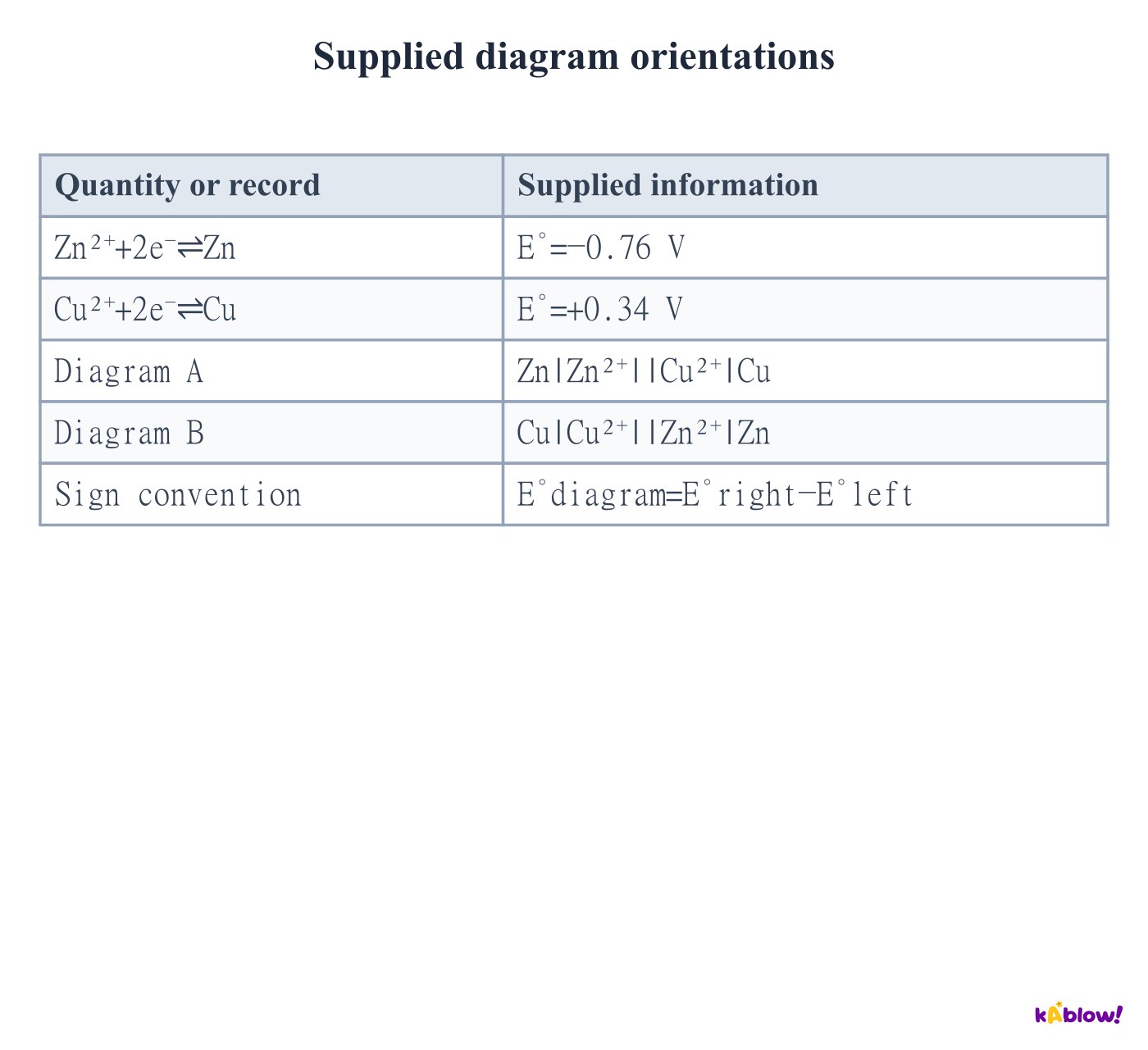
- For diagram A, E°right−E°left=.34−(−.76)=+1.10 V. Zinc oxidises on the left during galvanic discharge.
- Diagram B reverses the same half-cells, giving−.76−.34=−1.10 V. The physical preferred electron-transfer direction remains zinc to copper.
- The convenient spontaneous galvanic representation places oxidation left and reduction right. A specified reverse representation is still meaningful and carries the opposite signed emf.
Supplied diagram orientations
Calculate a standard cell potential
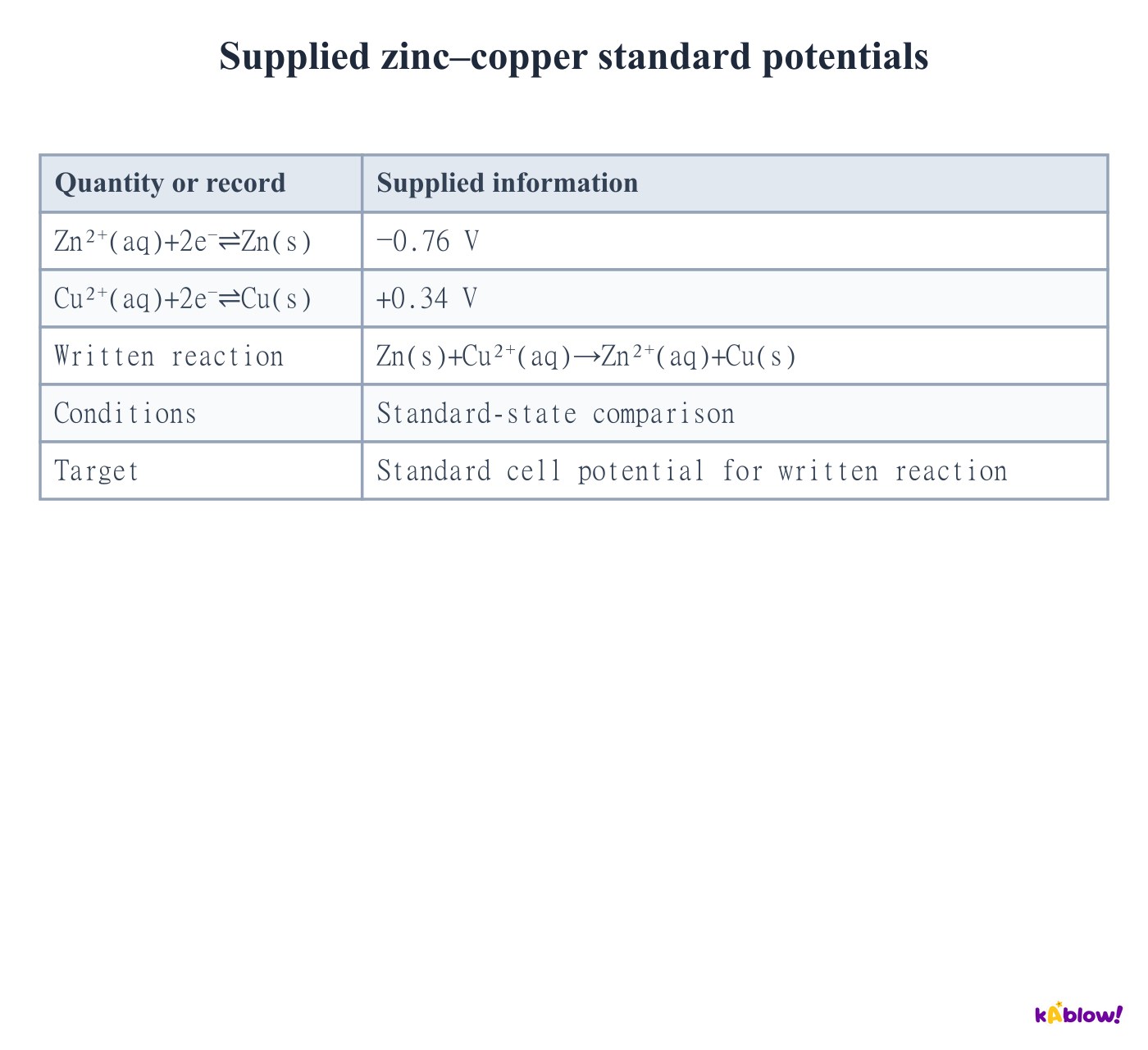
- Choose the reduction at the cathode and the oxidation at the anode. Using both tabulated values as reductions gives E°cell=E°cathode−E°anode.
- The supplied zinc–copper reaction has E°cell=.34−(−.76)=+1.10 V. Subtracting a negative adds its magnitude.
- Voltage is energy transferred per charge, not total energy. The measured voltage under load can be lower because of internal resistance and other losses.
Supplied zinc–copper standard potentials
Balance electrons without scaling potentials
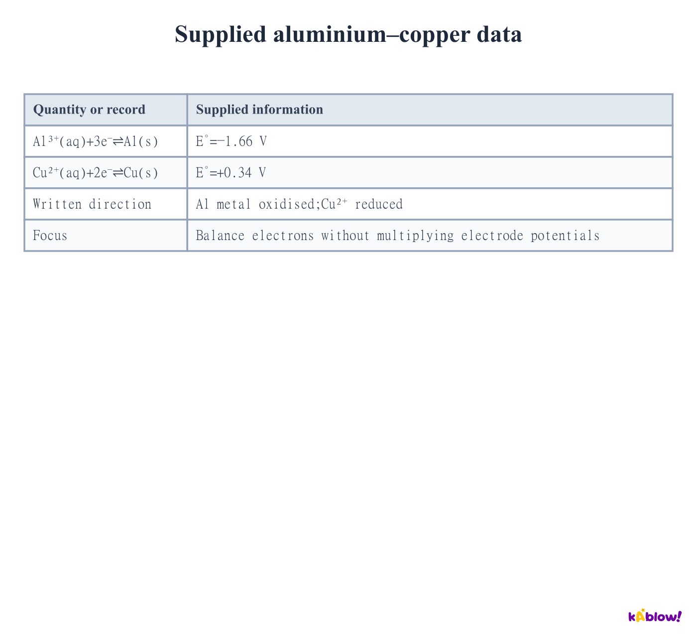
- Al oxidation releases three electrons per atom; Cu²⁺ reduction accepts two. Six electrons balance the half-equations.
- The net reaction is2Al+3Cu²⁺→2Al³⁺+3Cu. E°cell=.34−(−1.66)=+2.00 V.
- Do not multiply electrode potentials by2 or3 when scaling equations. They are intensive quantities; total Gibbs energy scales with reaction amount, while the voltage for matching electron transfer does not.
Supplied aluminium–copper data
Identify the oxidant and reductant on the correct sides
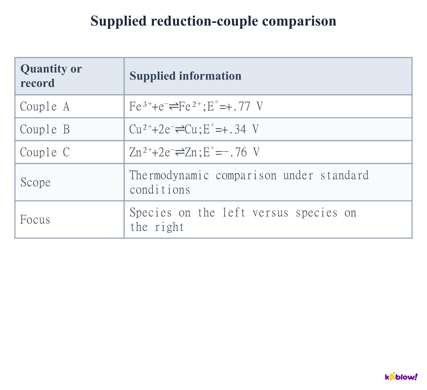
- The species on the left of a more-positive reduction couple has the stronger tendency to accept electrons under the comparison conditions.
- The species on the right of a more-negative couple is the stronger reducing agent. In the supplied set Fe³⁺ is the strongest oxidant and Zn metal the strongest reductant.
- An E° value belongs to an entire reduction couple with specified conditions, not to an element independently of its oxidation state and environment.
Supplied reduction-couple comparison
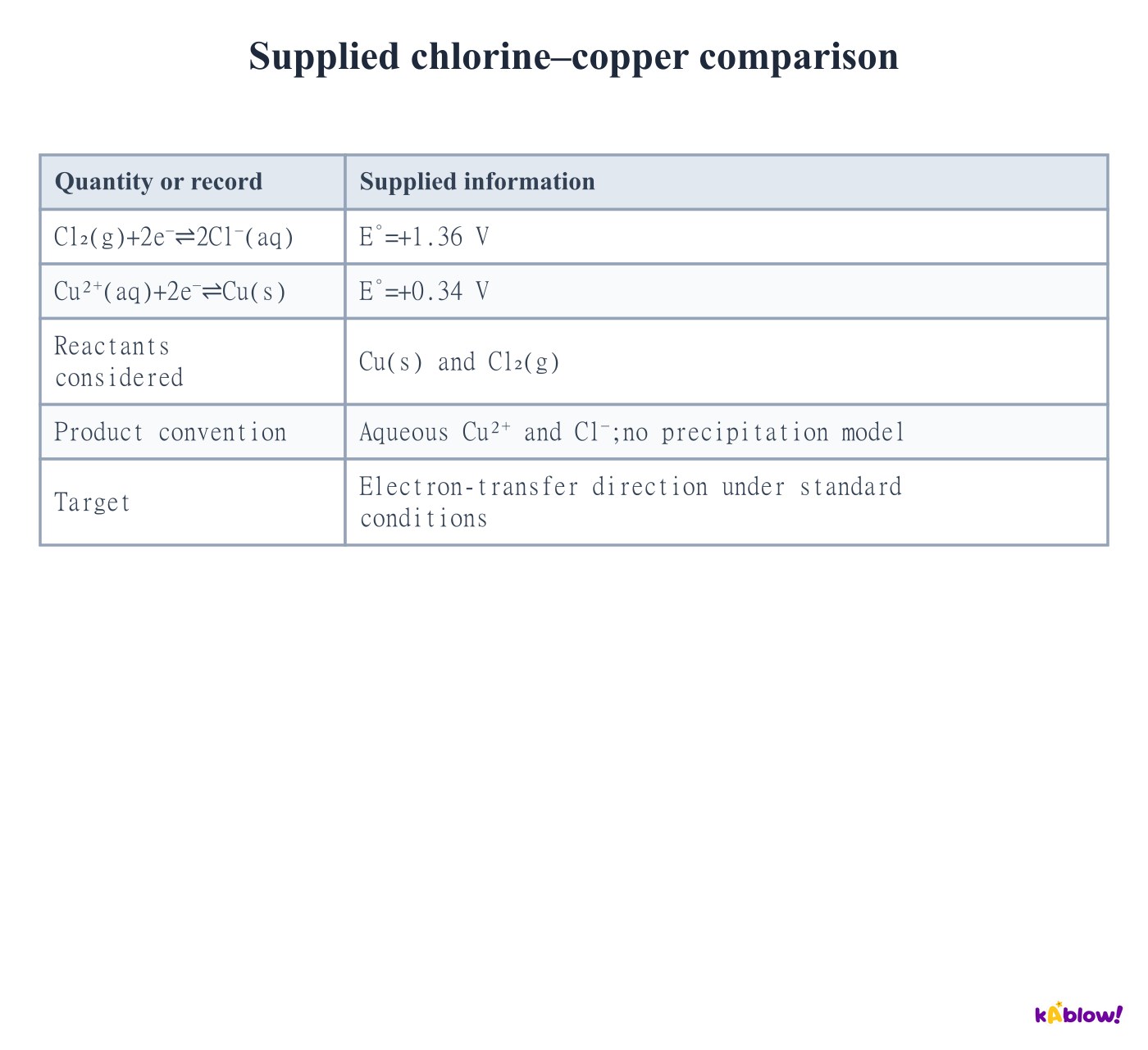
Correctly identify copper oxidation
- Chlorine has the more-positive reduction potential and accepts electrons:Cl₂+2e⁻→2Cl⁻.
- Copper metal supplies the electrons:Cu(s)→Cu²⁺+2e⁻. The reacting oxidised species is Cu metal, not Cu²⁺.
- Adding gives Cu+Cl₂→Cu²⁺+2Cl⁻ with E°cell=1.36−.34=+1.02 V. Do not silently replace these aqueous ions by a solid CuCl₂ product when using this potential dataset.
Supplied chlorine–copper comparison
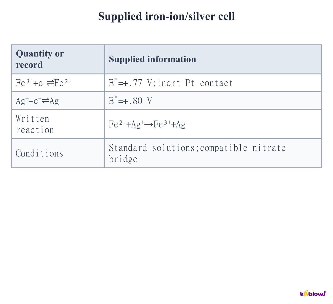
Use an inert contact for an ion/ion couple
- An Fe³⁺/Fe²⁺ half-cell has no conducting metal reactant in its reduction equation, so an inert platinum contact supplies the external electron path.
- With Ag⁺/Ag at+.80 V and Fe³⁺/Fe²⁺ at+.77 V, the written Fe²⁺+Ag⁺→Fe³⁺+Ag has E°cell=+.03 V.
- This small positive standard value is a thermodynamic indication for the specified reference states. Changes in composition can be important; it does not guarantee a rapid visible reaction in every mixture.
Supplied iron-ion/silver cell
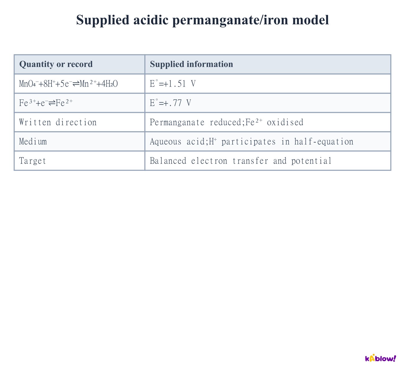
Include acid and electron multiplicity
- The supplied acidic permanganate reduction consumes8H⁺ and five electrons per MnO₄⁻. It forms Mn²⁺ and4H₂O.
- Five Fe²⁺ ions each release one electron, giving MnO₄⁻+8H⁺+5Fe²⁺→Mn²⁺+4H₂O+5Fe³⁺.
- E°cell=1.51−.77=+.74 V. Do not multiply the iron potential by five; keep the acidic conditions because changing the medium changes the relevant couple.
Supplied acidic permanganate/iron model
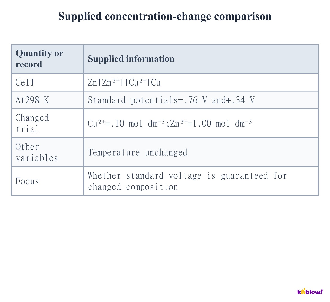
Distinguish standard from actual cell voltage
- Tabulated E° values support a standard-state calculation. Actual electrode potentials can depend on concentration, gas pressure and temperature.
- The changed copper concentration in the supplied trial means the standard1.10 V value is not guaranteed. AQA does not require the Nernst equation here.
- Comparisons must state which variables changed. Replacing a compatible bridge does not by itself justify a new standard reduction potential, but interfering reactions can alter the measured system.
Supplied concentration-change comparison
Use feasibility as a thermodynamic prediction
- A positive E°cell corresponds to a negative standard reaction Gibbs energy for the chosen direction and electron-transfer basis.
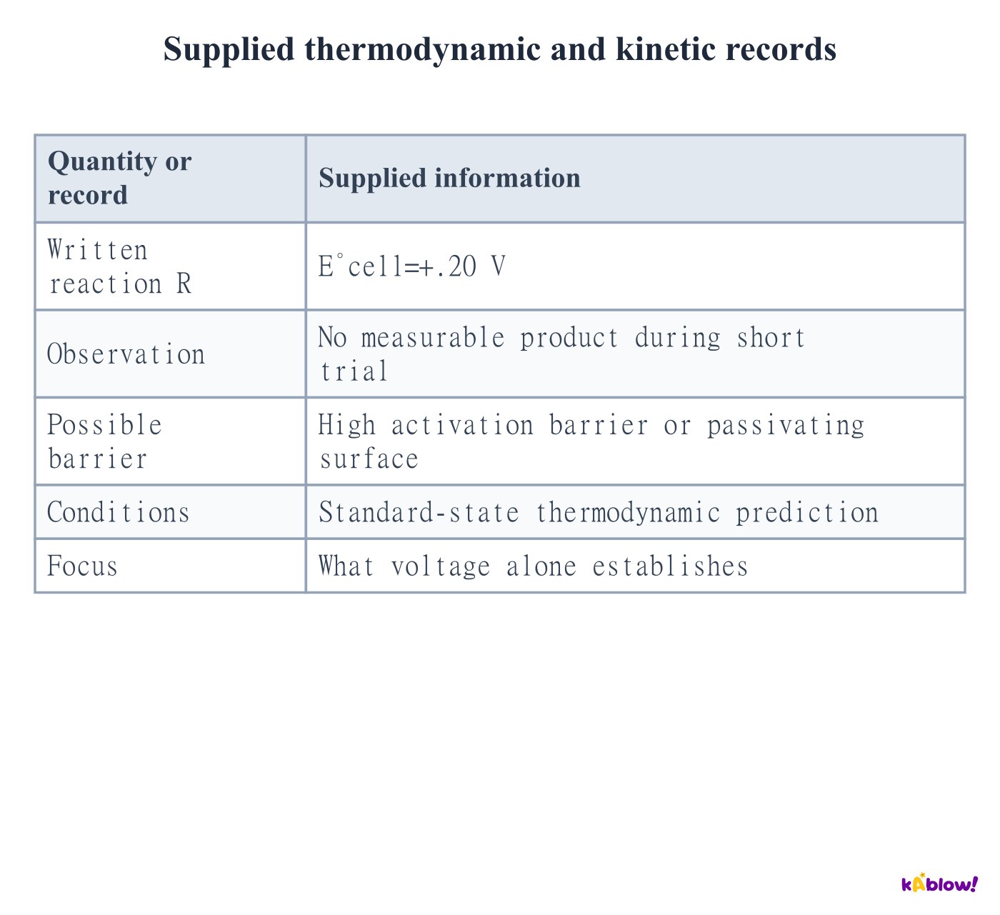
- This does not establish reaction speed. A large activation barrier or passivating layer can prevent an observable change during a short experiment.
- Actual nonstandard compositions can also alter the preferred direction. Distinguish thermodynamic driving force, kinetic limitations and the experimental observation.
Supplied thermodynamic and kinetic records
Measure emf with minimal loading
- For required practical8, assemble clean half-cells with a compatible bridge and a high-resistance voltmeter. Record lead orientation and the temperature and solution conditions.
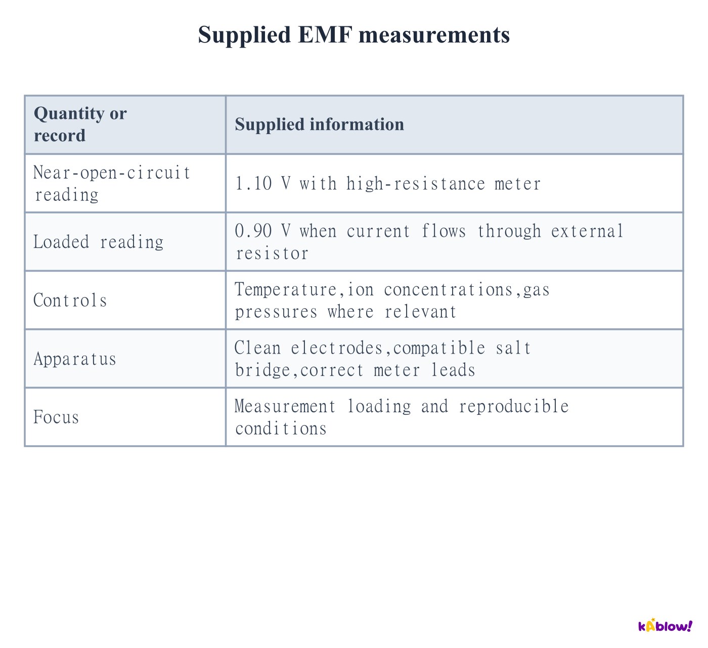
- A high input resistance draws very little current, reducing composition changes and loading losses. It approximates open-circuit emf rather than producing an exactly zero-current claim.
- The supplied loaded reading is lower than the near-open-circuit reading. Repeat measurements with the same preparation and investigate contamination, poor contacts and bridge incompatibility.
Supplied EMF measurements
Distinguish electrolyte, conductor and active redox material
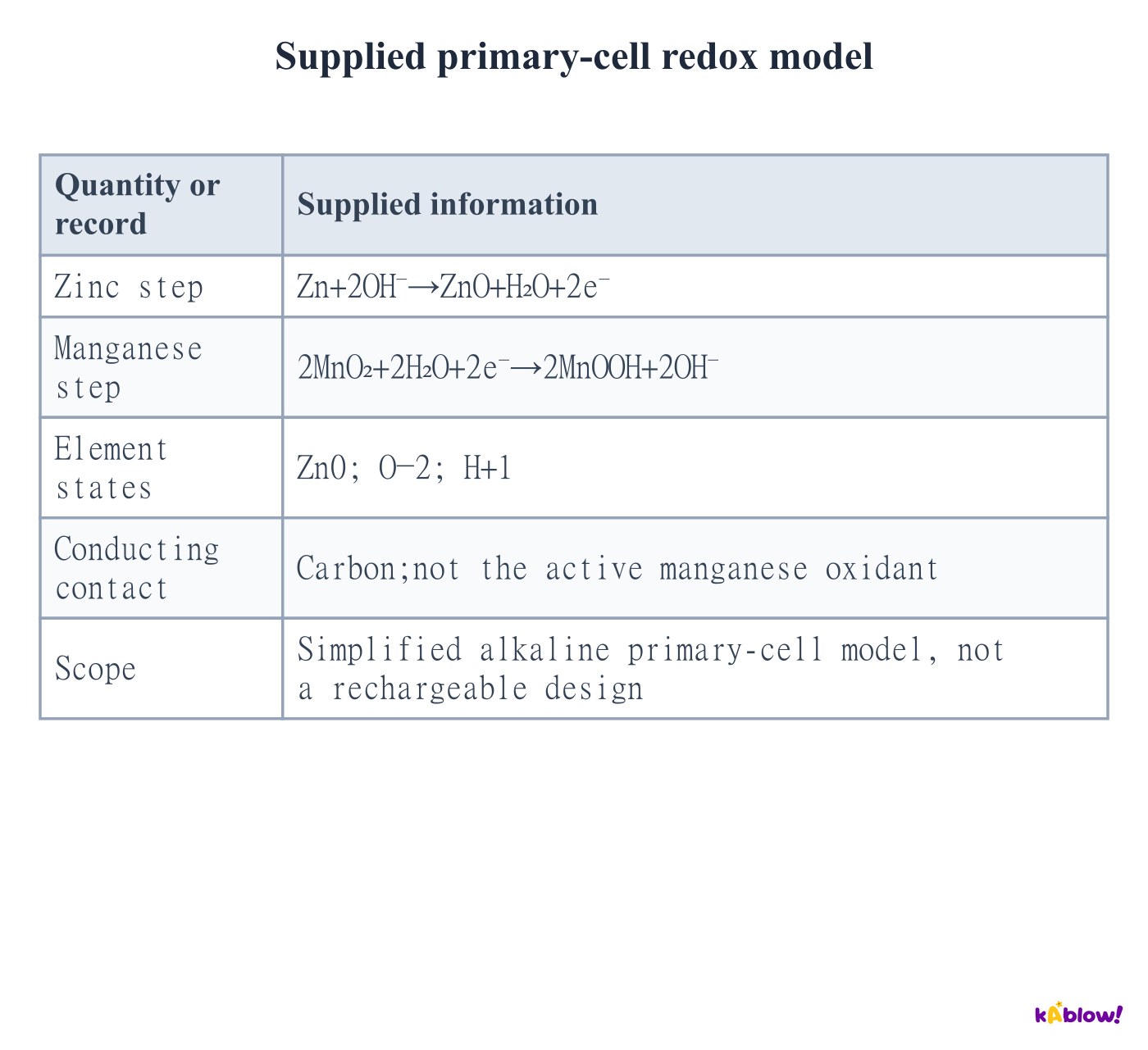
- In a simplified alkaline primary cell zinc is oxidised and manganese dioxide is reduced. The supplied half-equations cancel electrons and hydroxide when added.
- Carbon provides a conducting contact; the active manganese oxidant is MnO₂. An electrolyte conducts ions and is not automatically the positive active electrode material.
- The net supplied model is Zn+2MnO₂+H₂O→ZnO+2MnOOH. Primary cells are not designed for routine recharging; reversing an arbitrary applied voltage does not make them rechargeable.
Supplied primary-cell redox model
Reverse designed cell chemistry using electrical work
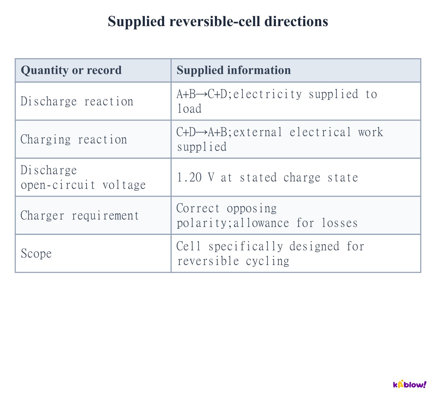
- A rechargeable cell is designed so an external supply can drive the discharge chemistry in reverse. Correct polarity and a suitable voltage/current regime are required.
- The charger must oppose the cell emf and account for losses. The energy input regenerates reactants; charging is not the cell creating energy.
- During charging the reaction sites reverse oxidation/reduction roles. Anode always means oxidation and cathode reduction, while their polarities differ from galvanic discharge.
Supplied reversible-cell directions
Combine lead–acid half-equations and series voltages
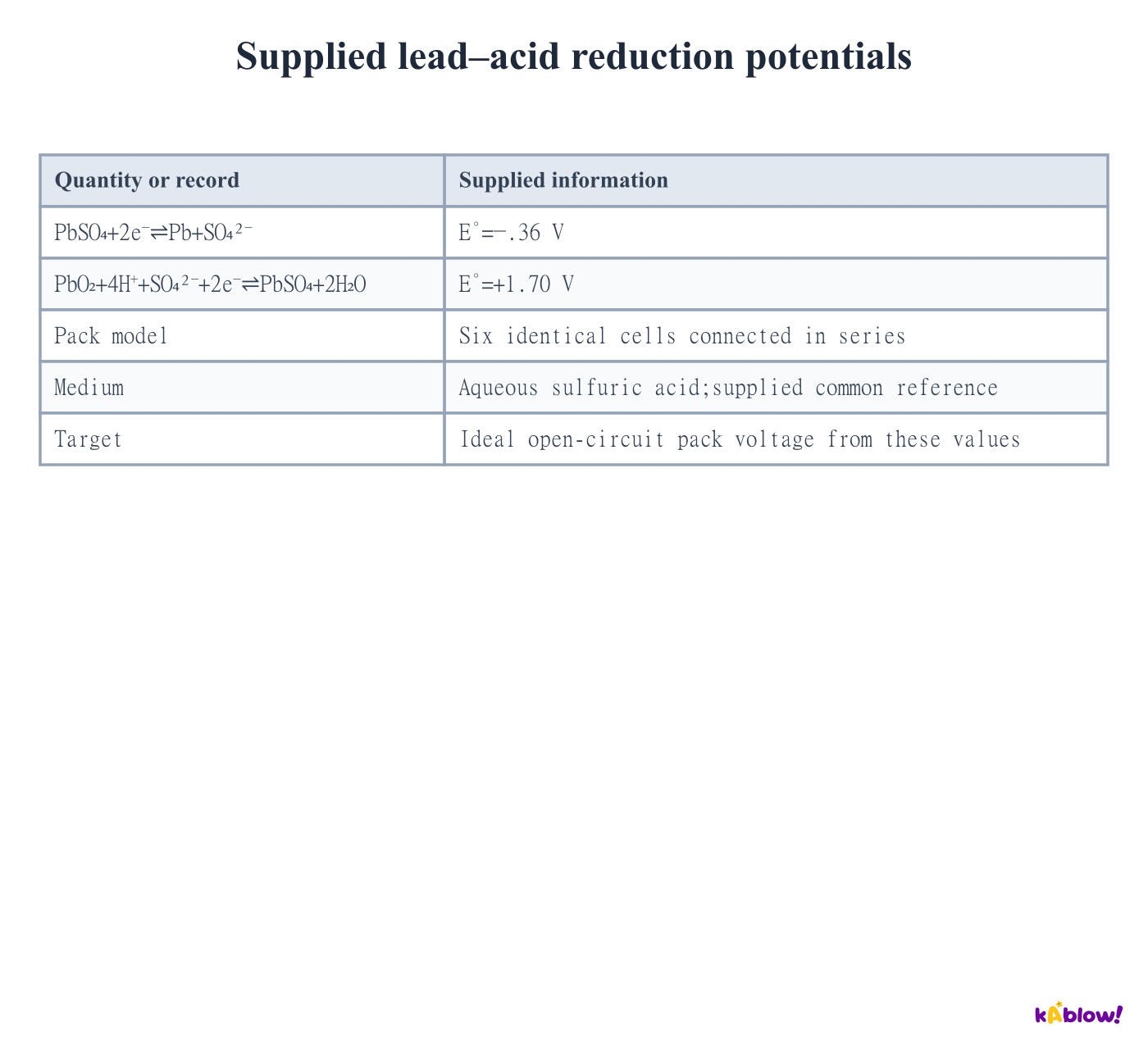
- For discharge, reverse the supplied lead reduction to oxidise Pb. The positive PbO₂ reduction consumes H⁺ and sulfate.
- Adding gives Pb+PbO₂+4H⁺+2SO₄²⁻→2PbSO₄+2H₂O. The supplied ideal cell potential is1.70−(−.36)=2.06 V.
- Six identical series cells give12.36 V in this model. Real voltage depends on acid activity, temperature and charge state. Lead toxicity, mass and corrosive acid affect handling and recycling choices.
Supplied lead–acid reduction potentials
Balance a nickel–cadmium discharge model
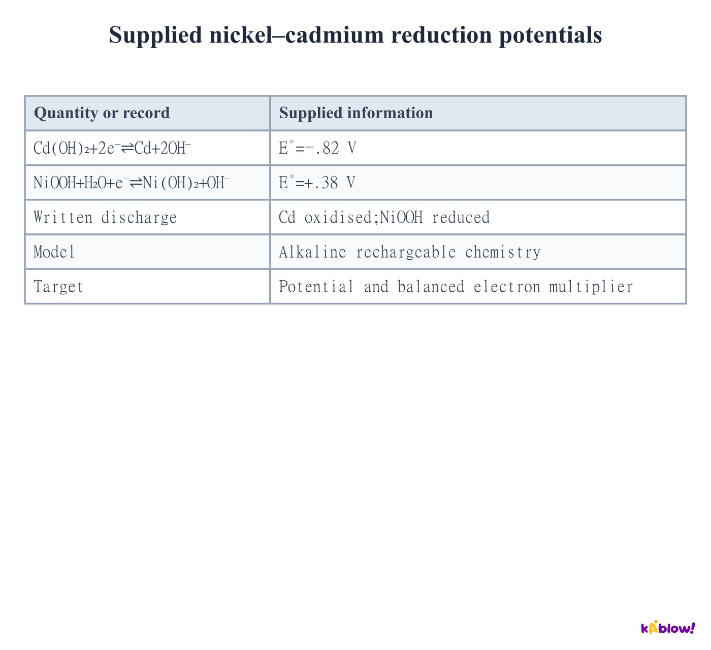
- Cadmium oxidises to Cd(OH)₂, releasing two electrons. Each NiOOH accepts one electron to form Ni(OH)₂, so multiply the nickel half-equation by two.
- The balanced net model is Cd+2NiOOH+2H₂O→Cd(OH)₂+2Ni(OH)₂. The supplied potential is.38−(−.82)=1.20 V.
- Nickel changes from+3 in NiOOH to+2 in Ni(OH)₂. Cadmium toxicity makes controlled collection and recycling important; memory-effect discussions do not mean every capacity loss has one cause.
Supplied nickel–cadmium reduction potentials
Use the AQA simplified lithium model precisely
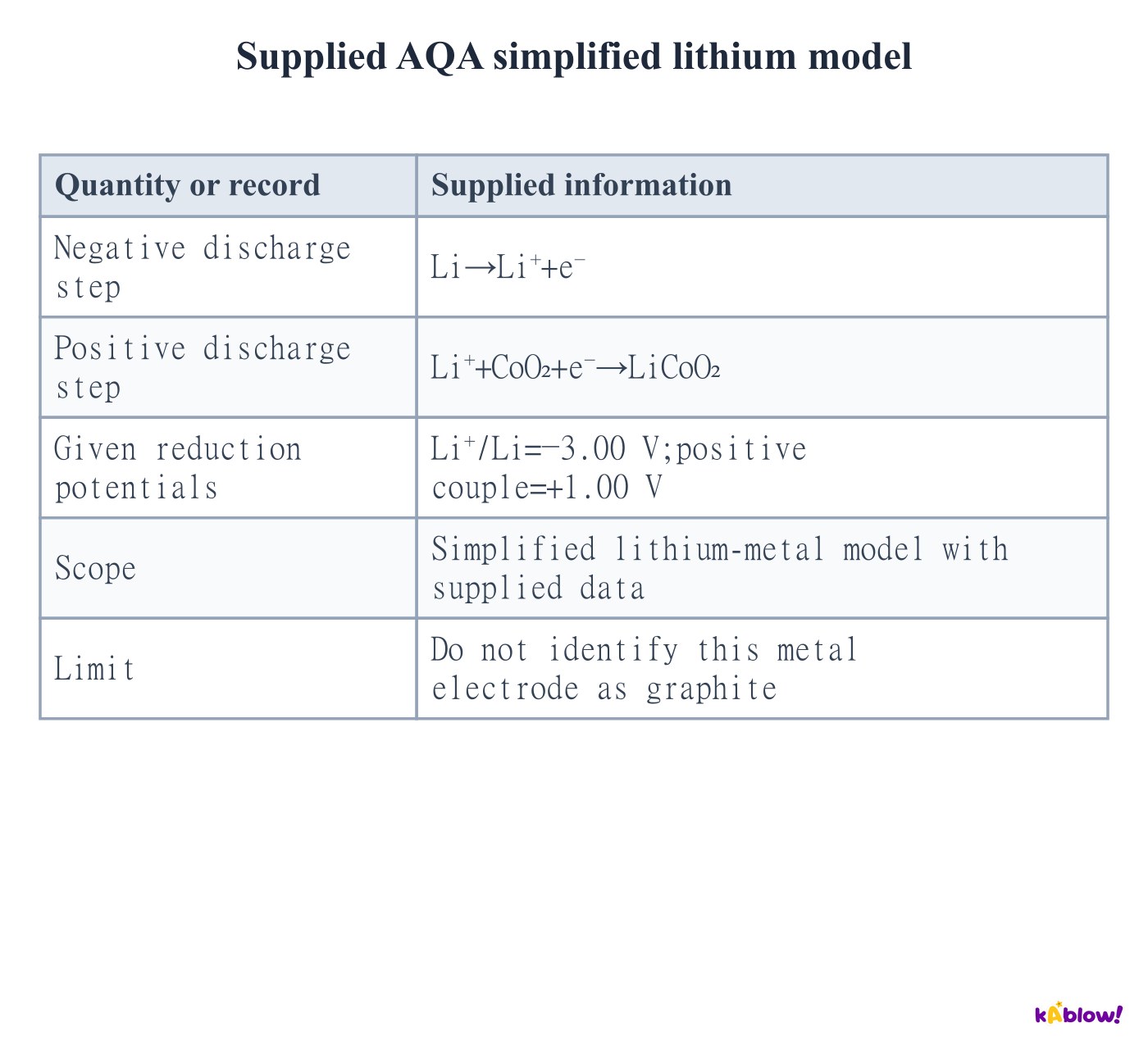
- The specified negative lithium-metal step is Li→Li⁺+e⁻. At the positive electrode Li⁺+CoO₂+e⁻→LiCoO₂.
- Adding gives Li+CoO₂→LiCoO₂. With the supplied reduction potentials, E°cell=1.00−(−3.00)=4.00 V.
- This is a simplified lithium-metal model used with given data. It does not describe a graphite negative electrode; actual lithium-ion cells commonly use intercalation rather than bulk lithium metal.
Supplied AQA simplified lithium model
Separate graphite intercalation from lithium metal
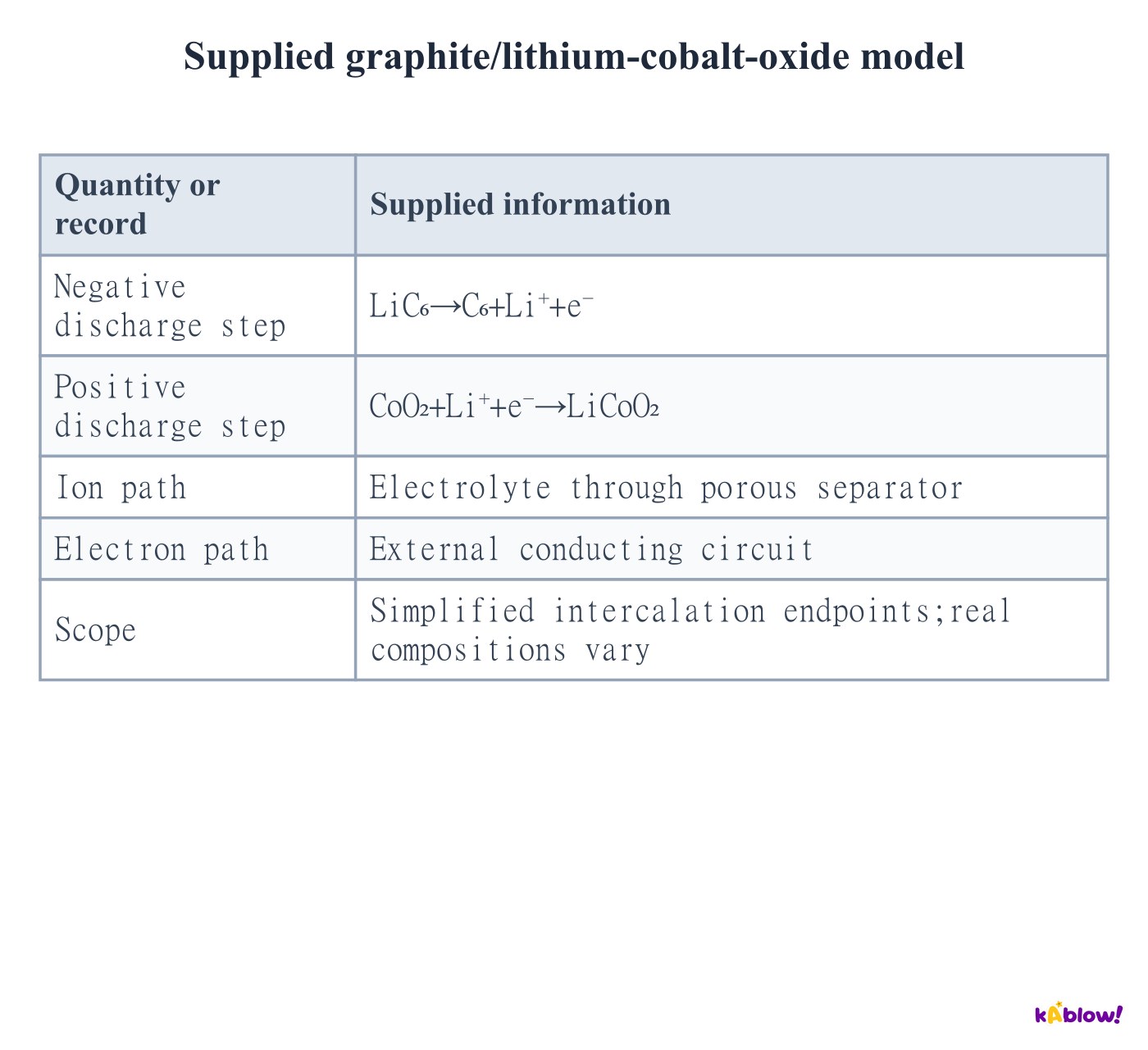
- In the supplied simplified graphite model, LiC₆ releases Li⁺ and an electron during discharge. Li⁺ crosses the electrolyte while electrons pass through the external load.
- The positive host accepts Li⁺ and electrons. Real electrodes operate over partial intercalation ranges, and voltage depends on chemistry and state of charge.
- A porous polymer separator prevents direct electronic contact while electrolyte carries ions. Many conventional cells use liquid electrolyte, so a separator must not be described automatically as a leakproof solid electrolyte. Cells can age even without the classic NiCd memory effect.
Supplied graphite/lithium-cobalt-oxide model
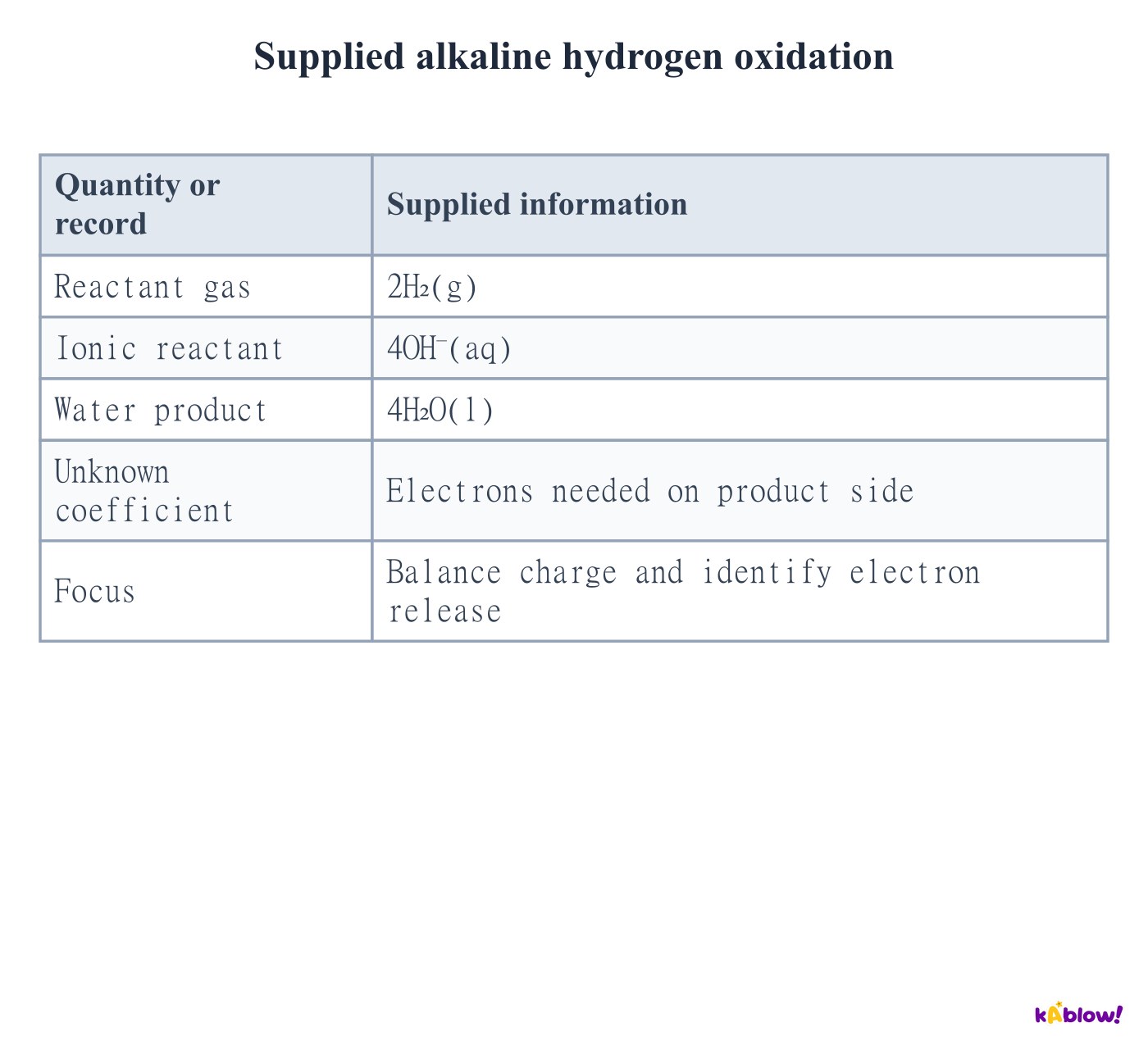
Balance alkaline hydrogen oxidation
- In an alkaline hydrogen–oxygen fuel cell the negative discharging electrode oxidises hydrogen. Hydroxide participates in its half-equation.
- On a four-electron basis,2H₂+4OH⁻→4H₂O+4e⁻. Both sides have eight hydrogen atoms, four oxygen atoms and total charge−4.
- Oxygen is not a reactant in this anode half-equation. It enters at the separate cathode; keeping the half-reactions separate is what permits external electron transfer.
Supplied alkaline hydrogen oxidation
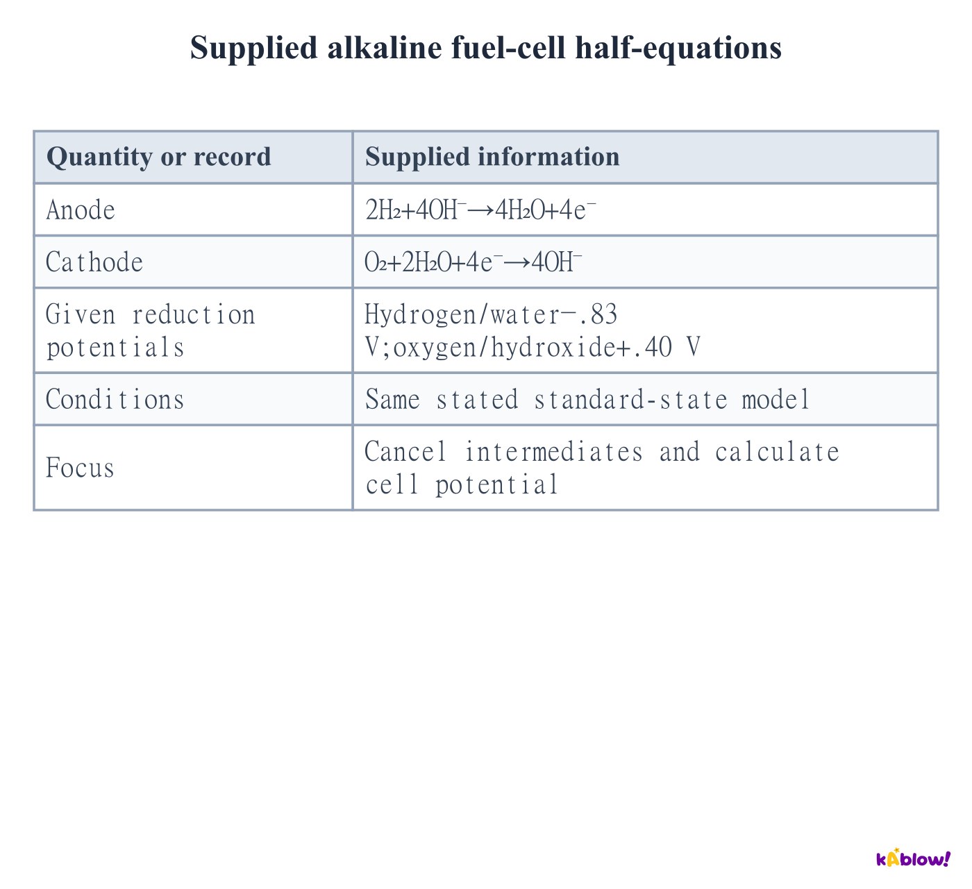
Combine alkaline fuel-cell half-equations
- The cathode reduction is O₂+2H₂O+4e⁻→4OH⁻. Add it to the alkaline hydrogen oxidation equation.
- Cancel four electrons and four hydroxide ions, then cancel two waters. The overall reaction is2H₂+O₂→2H₂O.
- The supplied reduction potentials give.40−(−.83)=1.23 V. This is a standard-state model value; operating voltage depends on temperature, pressures, water state and losses.
Supplied alkaline fuel-cell half-equations
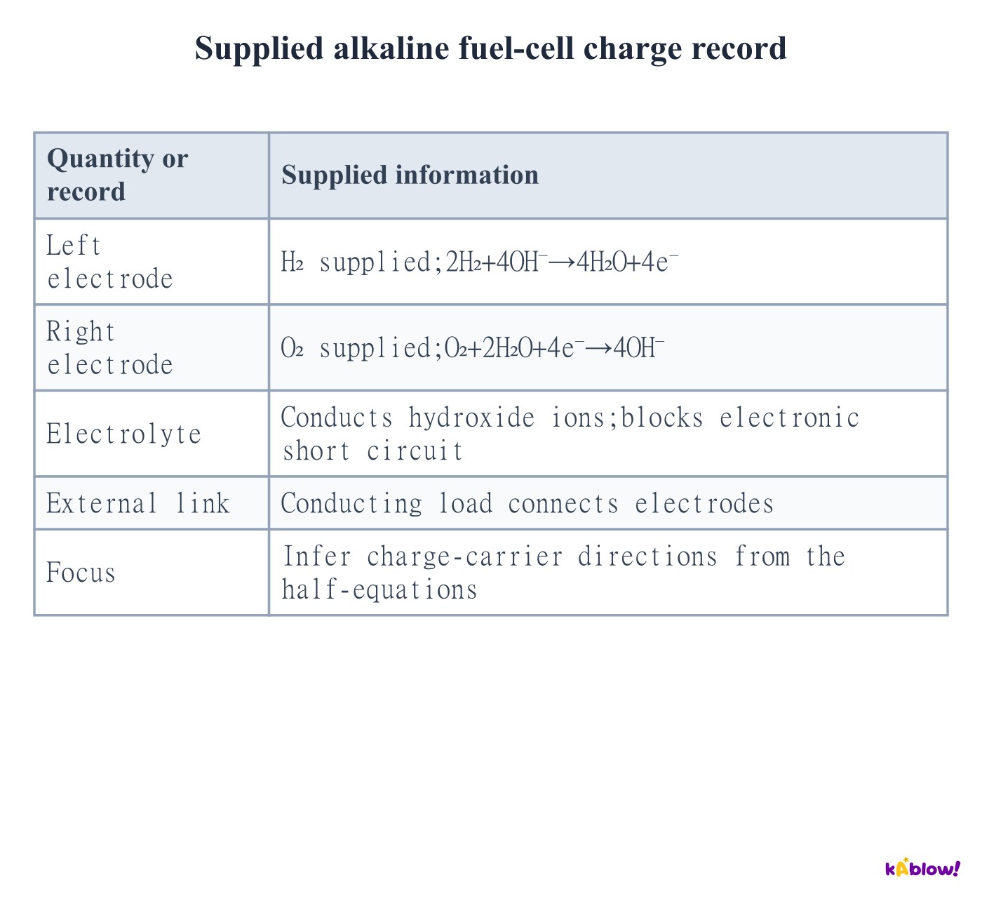
Infer alkaline charge-carrier directions
- Hydroxide forms at the oxygen cathode and is consumed at the hydrogen anode. Its net ionic transport is therefore toward the hydrogen side.
- Electrons leave the hydrogen electrode, pass through the external load, and enter the oxygen electrode. The electrolyte must not provide an electronic short circuit.
- A proton-exchange membrane cell instead transports H⁺ toward the oxygen side. Do not combine its proton diagram with alkaline OH⁻ half-equations.
Supplied alkaline fuel-cell charge record
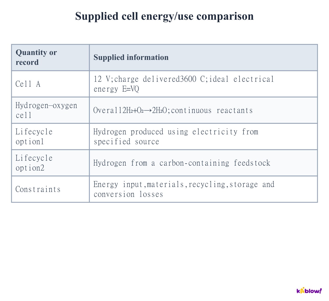
Compare energy output and whole-system impacts
- For the supplied constant-voltage model, electrical energy is VQ=12×3600=43200 J. Charge in coulombs is not energy, and voltage alone does not specify total stored energy.
- A hydrogen fuel cell can keep operating while fuel and oxidant are supplied. Water is the net local chemical product, but lifecycle impacts depend on hydrogen production, energy sources, equipment and materials.
- Hydrogen has high energy per mass and low gas energy per volume; storage and flammability matter. Rechargeable-cell resource extraction, ageing and recycling also matter. A cell is one electrochemical unit; battery can refer to one or more cells in common technical usage.
Supplied cell energy/use comparison
Diapos
Sign up free to view the lesson slides
Step through every slide for this topic — plus flashcards and revision notes — with a free account.
Questions d'entraînement
Aperçu gratuit — 8 sur 60 questions. Inscris-toi pour toutes les voir.
1.For the supplied zinc–copper system, which species releases electrons?
Medium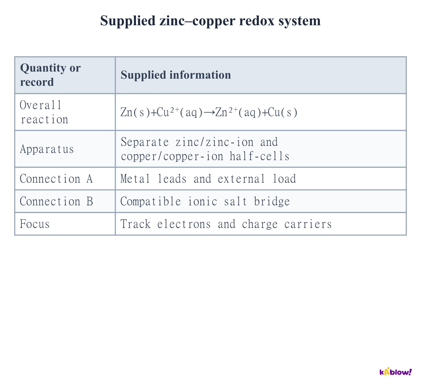
- AZn(s)
- BCu²⁺(aq)
- CZn²⁺(aq)
- DCu(s)
2.Which supplied experiment matches the stated AQA standard conditions?
Medium- AA
- BB
- CC
- DAll three
3.Using the supplied hydrogen reduction equation, how much H₂ forms when0.040 mol of electrons is accepted?
Medium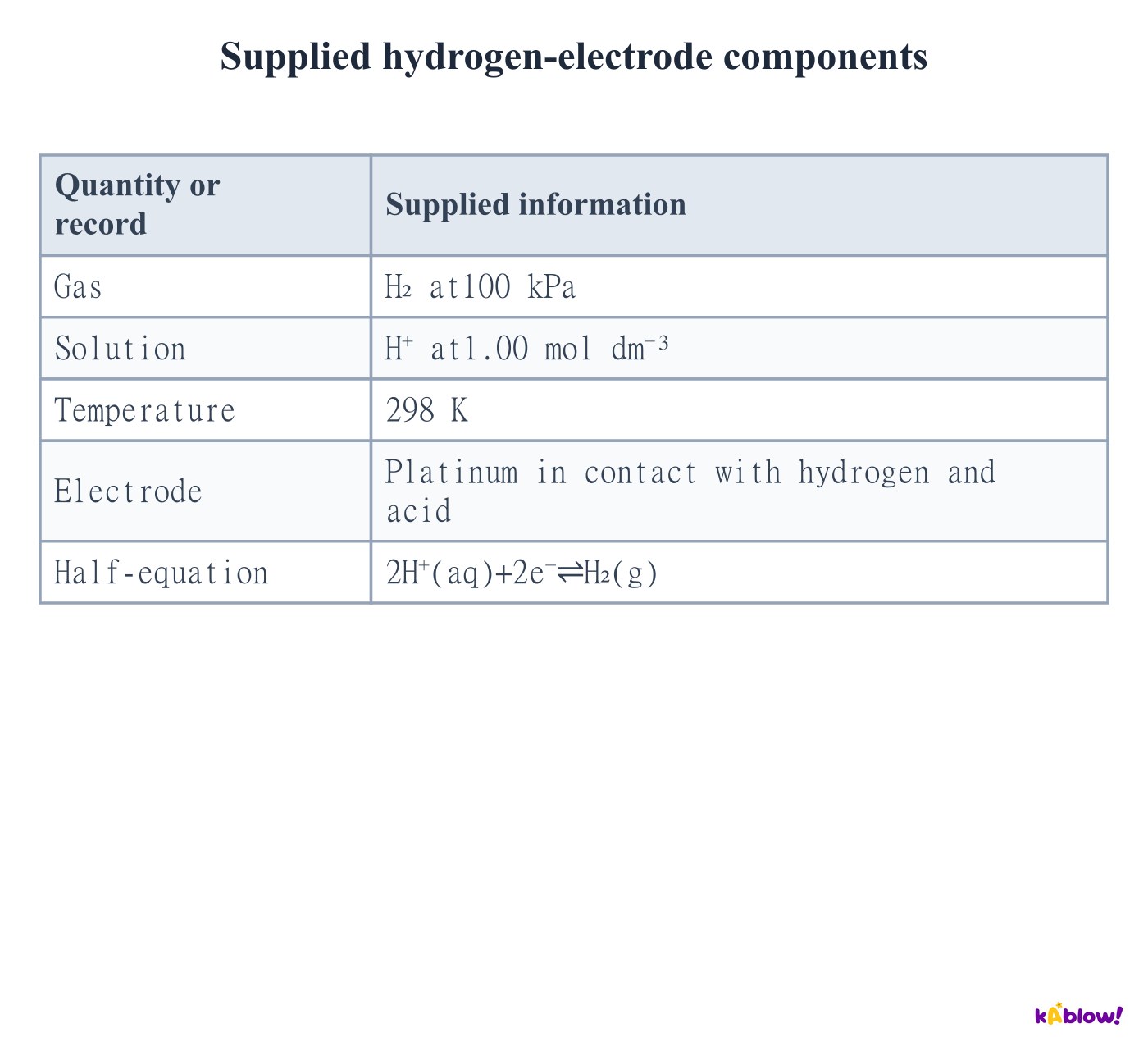
- A0.010 mol
- B0.020 mol
- C0.040 mol
- D0.080 mol
4.What signed voltage belongs to the supplied hydrogen-left/silver-right diagram?
Medium- A−0.80 V
- B0.00 V
- C+0.80 V
- D+1.60 V
5.What signed voltage belongs to the supplied hydrogen-left/zinc-right diagram?
Medium- A+0.76 V
- B−0.76 V
- C0.00 V
- D−1.52 V
6.Which bridge avoids the supplied interfering precipitation in the silver half-cell?
Medium- AA, KNO₃
- BB, KCl
- CEither, because all salts are inert
- DNeither, because salt bridges conduct electrons
7.Which bridge-ion migration supports charge balance in the supplied discharging cell?
Medium- AK⁺ toward zinc and NO₃⁻ toward copper
- BNO₃⁻ toward zinc and K⁺ toward copper
- CElectrons through the bridge toward copper
- DNeither ion can move
8.What does the comma between Fe²⁺ and Fe³⁺ mean in supplied notation B?
Medium- AA phase boundary
- BA salt bridge
- CSpecies in the same aqueous phase
- DAn external wire
Unlock all 60 questions, flashcards & more
Crée un compte gratuit pour voir toutes les questions, les diapos, les cartes mémo et les notes de révision de ce thème.