Current & Circuits
Apprends en jouant
Réponds à ces questions pour gagner de l'énergie, puis pêche et explore. Sans compte.
Notes de leçon
Circuit Diagrams
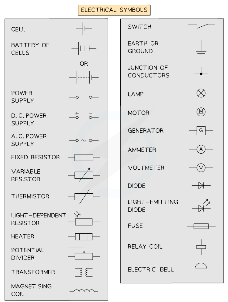
- Circuit symbols are used to represent electrical components in circuit diagrams and are universally recognised by scientists in any language.
- A cell converts chemical energy to electrical energy; the direction of conventional current flow is from the positive (longer side) to the negative (shorter side) terminal.
- A battery is a power source made up of multiple cells.
- A switch turns the circuit on (closed) or off (open), allowing or preventing the flow of current.
- A voltmeter measures potential difference and is connected in parallel; an ammeter measures current and is connected in series.
- A fixed resistor increases resistance to limit current; a variable resistor has a slider to change its resistance.
- An LDR (light-dependent resistor) has resistance that decreases as light intensity increases; a thermistor has resistance that decreases as temperature increases.
- A diode (including an LED) allows current to flow in one direction only.
Electrical symbols used in circuit diagrams
Electric Current
- Electric current is the rate of flow of charge carriers, measured in amperes (A).
- Charge is measured in coulombs (C); the greater the flow of charge, the greater the current.
- The equation for current is I = Δq / Δt, where I is current (A), Δq is charge (C), and Δt is time (s).
- Conventional current is defined as the flow of positive charge from the positive terminal to the negative terminal of a cell.
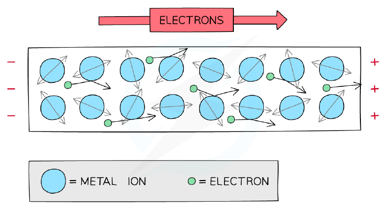
- In metal wires, current is a flow of electrons, which are negatively charged and flow from the negative terminal to the positive terminal — opposite to conventional current.
- Direct current (dc) flows in one direction only and is produced by cells and batteries.
- Current is measured using an ammeter connected in series; an ideal ammeter has zero resistance.
Potential difference in a circuit
Electric Potential Difference
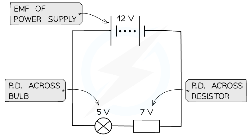
- Potential difference (p.d.), also called voltage, is the work done per unit charge on moving a positive charge between two points along the path of the current.
- Potential difference is measured in volts (V) and calculated as V = W / q, where W is work done (J) and q is charge (C).
- One volt is equal to one joule per coulomb: 1 V = 1 J C⁻¹.
- In a d.c. circuit, the potential difference is provided by cells or batteries; each cell has a positive terminal (high potential) and a negative terminal (low potential).
- A battery is a collection of cells arranged positive terminal to negative terminal.
- The electronvolt (eV) is the amount of energy needed to move an electron through a potential difference of one volt; 1 eV = 1.6 × 10⁻¹⁹ J.
Electrical Conductors & Insulators
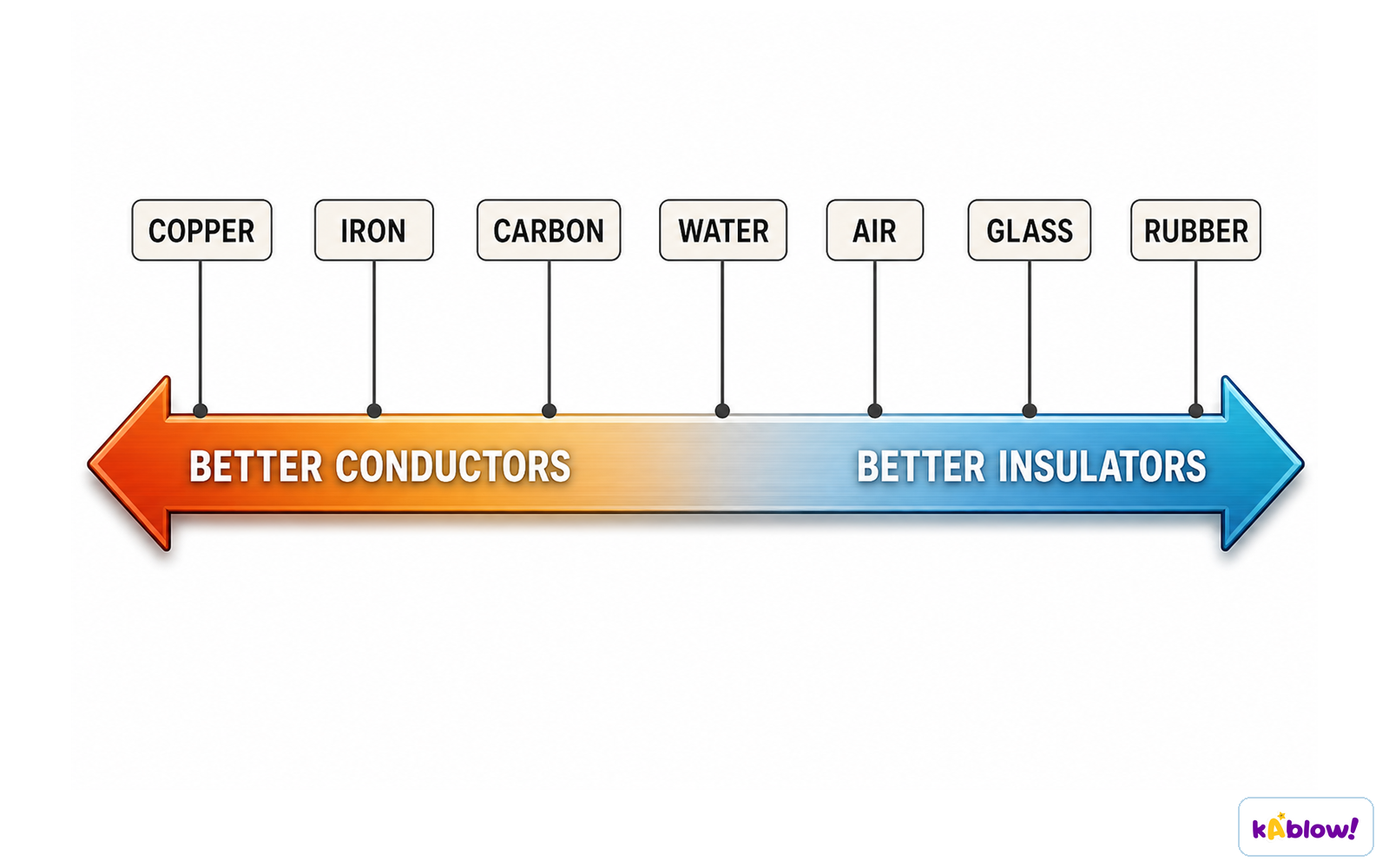
- A conductor is a material that allows charge (usually electrons) to flow through it easily; examples include silver, copper, aluminium, and steel.
- Conductors tend to be metals and are made up of positively charged metal ions within a sea of delocalised electrons.
- Metals are excellent conductors because they contain a large number of delocalised electrons that are able to flow easily.
- An insulator is a material with very few free charges, so it does not allow the flow of charge easily; examples include rubber, plastic, glass, and wood.
- Insulators can conduct static electricity when charge builds up on their surface; when a charged insulator contacts a conductor, the charge can be transferred.
Conductors and insulators
Electric Resistance
- As electrons move through a conductor, they collide with metal ions and transfer some of their electrical potential energy to the positive ions, raising the internal energy of the metal and causing heating.
- Resistance is defined as the ratio of the potential difference across a component to the current flowing through it: R = V / I.
- The unit of resistance is the ohm (Ω); 1 Ω = 1 kg m² s⁻³ A⁻².
- The higher the resistance of a component, the lower the current flowing through it, and vice versa.
- An ideal voltmeter has infinite resistance so no current passes through it; an ideal ammeter has zero resistance so all the current passes through it.
- Copper has a low electrical resistance, making it an ideal material for making wires.
Resistance in a conductor
Electrical Resistivity
- The resistance of a sample depends on the material it is made of, its length, and its cross-sectional area.
- The resistance of a conductor is directly proportional to its length and inversely proportional to its cross-sectional area.
- Resistivity is the property describing the extent to which a material opposes the flow of electric current through it.
- Resistivity is defined as the resistance per unit length of a material with unit cross-sectional area: ρ = RA / L.
- Resistivity is measured in ohm-metres (Ω m) and is a property of the material.
- Conductors such as metals have low values of resistivity, making them ideal for wires; insulators have very high resistivity, so virtually no current flows through them.
- The cross-sectional area of a wire is modelled as a circle: A = πr² or A = πd²/4.
I-V Characteristics
- Ohm's law states that for a component at constant temperature, the current through it is proportional to the potential difference across it: V = IR.
- An electrical component obeys Ohm's law if its graph of current against potential difference is a straight line through the origin.
- A fixed resistor is an ohmic component; a filament lamp is a non-ohmic component.
- For an ohmic component, resistance can be determined from the gradient of an I-V graph: if I is on the y-axis and V on the x-axis, R = 1/gradient; if V is on the y-axis and I on the x-axis, R = gradient.
- A semiconductor diode is forward-biased when current flows in the direction of the arrowhead symbol, showing a sharp increase in current; it is reverse-biased when it does not conduct and current is zero.
- A filament lamp behaves approximately as an ohmic component at low voltages, but as voltage increases, the filament temperature and resistance increase, making it non-ohmic with a curve of decreasing gradient.
- Non-ohmic devices include lamps, LEDs, thermistors, and LDRs.
Series & Parallel Circuits
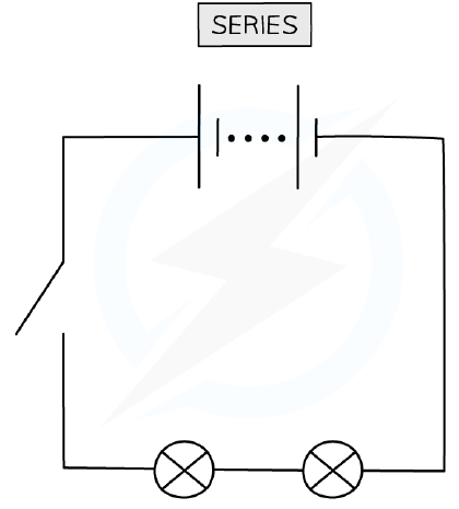
- In a series circuit, the current is the same at any point and the potential difference is split across all components depending on their resistance.
- The combined resistance of resistors in series is the sum of the individual resistances: R = R₁ + R₂ + R₃.
- Connecting more resistors in series increases the overall resistance; the combined resistance is more than the resistance of any individual component.
- In a parallel circuit, the total current is equal to the sum of the currents in each parallel branch, and the potential difference is the same across each loop.
- The reciprocal of the combined resistance of resistors in parallel is the sum of the reciprocals of the individual resistances: 1/R = 1/R₁ + 1/R₂.
- Connecting more resistors in parallel decreases the overall resistance; the combined resistance is less than the resistance of any individual component.
A simple series circuit
Electrical Power
- When an electrical current does work against electrical resistance, electrical energy is dissipated as thermal energy in the surroundings.
- The amount of heat produced depends on the current (greater current produces more heat) and the resistance (higher resistance produces more heat for a given current).
- Electrical power is the rate of change of work done: P = E / t = W / t, where P is power (W), E is energy transferred (J), and t is time (s).
- Power dissipated by an electrical device can be written as P = IV, where I is current (A) and V is potential difference (V).
- Using Ohm's law, power can also be written as P = I²R = V²/R.
- The energy transferred can be written as E = VIt.
- For a given resistor, doubling the current (or voltage) yields an electrical power four times greater.
Sources of Electrical Energy
- An electric cell stores chemical energy that can be transferred to electrical energy.
- Chemical cells (batteries) utilise chemical reactions to provide a potential difference; they can be rechargeable or non-rechargeable.
- Non-rechargeable batteries (e.g. alkaline AA) can only be used once; rechargeable cells (e.g. lithium-ion, lead-acid) can be used many times as the chemical reaction is reversed when charged.
- Solar cells (photovoltaic cells) convert electromagnetic radiation (photons) from the Sun into electrical energy.
- Advantages of single-use batteries include high energy density, portability, and low cost; disadvantages include limited power supply, high internal resistance, and disposal issues.
- Advantages of rechargeable batteries include high energy density, high electrical efficiency, and low internal resistance; disadvantages include degradation over time and higher cost.
- Solar cells have an unlimited supply of clean energy but variable output dependent on weather and require large investment and areas.
Electromotive Force & Internal Resistance
- Electromotive force (e.m.f.) is the amount of chemical energy converted to electrical energy per coulomb of charge when a charge passes through a power supply.
- E.m.f. is measured in volts (V) and is also the potential difference across the cell when no current is flowing (open circuit).
- E.m.f. is measured by connecting a high-resistance voltmeter across the terminals of the cell in an open circuit.
- All power supplies have some internal resistance (r) between their terminals, which causes charge circulating to dissipate some electrical energy from the power supply itself, making the cell warm.
- A cell can be considered as a source of e.m.f. with an internal resistance connected in series; the e.m.f. is the sum of the potential differences: ε = I(R + r).
- The potential difference across the internal resistance is called the 'lost volts' (Vr = Ir); the terminal p.d. is the p.d. across the load resistor (VR = IR).
- E.m.f. is the total, or maximum, voltage available to the circuit.
Variable Resistance
- A thermistor is a non-ohmic, sensory resistor whose resistance varies with temperature; most are negative temperature coefficient (ntc), meaning resistance decreases as temperature increases.
- Thermistors are used as temperature sensors in circuits such as ovens, fire alarms, and digital thermometers.
- A light-dependent resistor (LDR) is a non-ohmic, sensory resistor whose resistance decreases as light intensity increases.
- In the dark, an LDR's resistance is very large (millions of ohms); in bright light, its resistance is small (tens of ohms).
- LDRs are used in automatic street lights and garden lights that switch on when it gets dark.
- A potentiometer is similar to a variable resistor connected as a potential divider to give a continuously variable output voltage; it can be used to compare potential differences in different parts of a circuit.
- Moving the slider on a potentiometer changes the resistance (and hence potential difference) of the upper and lower parts, allowing maximum or minimum output voltage.
Diapos
Sign up free to view the lesson slides
Step through every slide for this topic — plus flashcards and revision notes — with a free account.
Questions d'entraînement
Aperçu gratuit — 8 sur 63 questions. Inscris-toi pour toutes les voir.
1.What is the unit of electric current?
Easy- AVolt
- BAmpere
- CCoulomb
- DOhm
2.Which of the following is the correct definition of the coulomb?
Easy- AThe charge transferred by a current of 1 A in 1 s
- BThe charge on one electron
- CThe energy transferred by a potential difference of 1 V
- DThe resistance when 1 V drives 1 A
3.A charge of 60 μC flows through a conductor in 140 ms. What is the current in the conductor?
Easy- A0.43 mA
- B0.43 A
- C4.3 mA
- D430 mA
4.Which of the following statements about conventional current and electron flow is correct?
Medium- AConventional current flows from negative to positive; electrons flow from positive to negative.
- BConventional current flows from positive to negative; electrons flow from negative to positive.
- CBoth conventional current and electron flow are from positive to negative.
- DBoth conventional current and electron flow are from negative to positive.
5.A student builds a circuit with a 6.0 V battery and two resistors of 4.0 Ω and 8.0 Ω connected in parallel. What is the total current drawn from the battery?
Medium- A0.50 A
- B2.25 A
- C1.50 A
- D0.75 A
6.A wire of length L and cross-sectional area A has resistance R. If the wire is stretched to twice its original length while its volume remains constant, what is its new resistance?
Medium- A2R
- B4R
- CR/2
- DR/4
7.Which of the following best explains why an ideal ammeter should have zero resistance?
Medium- ASo that it does not change the current it is measuring
- BSo that it can measure very large currents
- CSo that it does not affect the potential difference across the component
- DSo that it can be connected in parallel with the component
8.Which of the following is an ohmic conductor?
Medium- AFilament lamp
- BLight-emitting diode
- CFixed resistor at constant temperature
- DThermistor
Unlock all 63 questions & more
Crée un compte gratuit pour voir toutes les questions, les diapos, les cartes mémo et les notes de révision de ce thème.