Series and parallel circuits
遊んで学ぼう
問題に答えてエネルギーを集めたら、釣りや探検を楽しもう。アカウント不要。
レッスンノート
Series Circuits
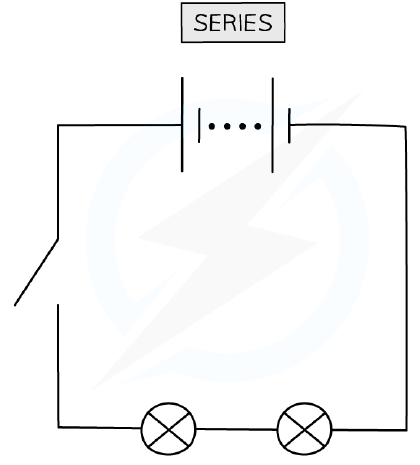
- A series circuit has components connected end to end in a single loop.
- The current is the same at all points in a series circuit.
- The total potential difference of the power supply is shared between the components.
- The total resistance is the sum of the individual resistances: R = R₁ + R₂ + R₃ ...
- Adding more resistors in series increases the overall resistance because charge must pass through more components.
- If one component breaks, the whole circuit stops working, and components cannot be controlled separately.
A simple series circuit
Parallel Circuits
- A parallel circuit has components connected on separate branches.
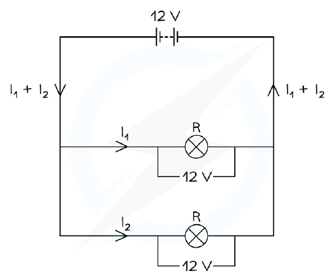
- The potential difference across each component is the same.
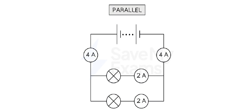
- The total current from the supply is the sum of the currents through the separate branches.
- The total resistance of two resistors in parallel is less than the resistance of the smallest individual resistor.
- Adding more resistors in parallel decreases the overall resistance because each resistor provides an extra path for charge to flow.
- Components can be controlled individually, and if one stops working, the others continue to function.
Potential difference in a parallel circuit
Comparing Series and Parallel Circuits
- In series, current is the same everywhere; in parallel, current splits at junctions.
- In series, potential difference is shared; in parallel, potential difference is the same across each branch.
- In series, total resistance increases with more components; in parallel, total resistance decreases.
- The current in each parallel branch is only identical if the resistance of each branch is identical.
- Some circuits include both series and parallel parts.
Calculation of current splitting at a junction in a parallel circuit
Resistors in Series and Parallel
- For resistors in series, the combined resistance is the sum of individual resistances.
- For resistors in parallel, the combined resistance is less than the smallest individual resistance.
- In parallel, each resistor creates an extra path for charge, allowing more charge to flow overall and reducing resistance.
- Increasing the number of resistors in series increases resistance because charge has more components to pass through.
- In a series circuit, the total voltage is the sum of the voltages across each component.
Electrical Components and I-V Graphs
- Fixed resistors: current is directly proportional to potential difference; the I-V graph is a straight line through the origin.
- Filament lamps: resistance increases as temperature increases; the I-V graph curves, showing current increasing at a slower rate.
- Diodes: allow current in one direction only (forward bias); in reverse bias, resistance is very high and no current flows.
- LDRs: resistance decreases as light intensity increases.
- Thermistors: resistance decreases as temperature increases.
- LDRs and thermistors are sensory resistors used in light sensors and temperature sensors.
Testing Components
- To investigate resistance variation, use a circuit with an ammeter in series and a voltmeter in parallel with the component.
- A variable resistor changes the current through the component.
- For filament lamps and diodes, vary current and measure voltage; calculate resistance using R = V/I.
- For LDRs, vary light intensity; for thermistors, vary temperature; record voltage and current to calculate resistance.
- Ensure the component is connected to a low voltage supply (below 15 V) to avoid overheating.
- Wait a few seconds before taking readings to allow the component to react.
Core Practical: Investigating Circuits
- Investigate the relationship between potential difference, current and resistance for a resistor and a filament lamp.
- Vary voltage using a variable resistor and record current for each voltage; take multiple readings and calculate averages.
- Switch off the circuit between readings to prevent heating.
- Plot an I-V graph: straight line through origin for fixed resistor; curve for filament lamp.
- Test series and parallel circuits: measure voltage and current, calculate resistance.
- In series, total resistance is the sum of individual resistances; in parallel, total resistance is less than either individual resistance.
AC and DC
- Direct current (d.c.): current flows steadily in one direction; cells and batteries produce d.c.
- Alternating current (a.c.): current continuously changes direction; mains electricity is a.c.
- In the UK, mains electricity has a frequency of 50 Hz and a potential difference of about 230 V.
- A.c. is represented by a sine wave on an oscilloscope; d.c. is a straight line.
- A d.c. power supply has fixed positive and negative terminals; an a.c. supply has two identical terminals.
Mains Electricity and Safety
- Mains electricity is an a.c. supply with live, neutral and earth wires.
- Live wire (brown) carries the alternating potential difference; it is the most dangerous.
- Neutral wire (blue) completes the circuit and is close to 0 V.
- Earth wire (green and yellow stripes) is a safety wire that prevents the appliance from becoming live.
- If a fault occurs, the earth wire provides a low resistance path, causing a surge of current that melts the fuse and cuts off the supply.
- The live wire has a potential difference of about 230 V, so contact can be lethal.
スライド
練習問題
無料プレビュー — 61問中8問。すべて見るには登録を。
1.In a series circuit, how does the current at one point compare with the current at another point?
Easy- AThe current is the same at all points
- BThe current is larger near the power supply
- CThe current splits between the components
- DThe current is smaller after each component
2.In a parallel circuit, what happens to the current at a junction?
Easy- AIt splits into the separate branches
- BIt stays the same in every branch
- CIt is destroyed at the junction
- DIt is shared equally whatever the resistances are
3.A 12 V battery is connected to two identical lamps in series. What is the potential difference across each lamp?
Easy- A12 V
- B6 V
- C24 V
- D0 V
4.A 12 V battery is connected to two identical lamps in parallel. What is the potential difference across each lamp?
Easy- A12 V
- B6 V
- C24 V
- D0 V
5.Which statement about the total resistance of two resistors in parallel is correct?
Medium- AIt is less than the resistance of the smallest individual resistor
- BIt is the sum of the two resistances
- CIt is greater than either individual resistance
- DIt is equal to the larger of the two resistances
6.Which of the following are true for components connected in series? (select all that apply)
Medium- AThe current is the same through each component
- BThe total potential difference of the supply is shared between the components
- CThe total resistance is the sum of the individual resistances
- DThe potential difference is the same across each component
- EThe current splits between the components
7.Which of the following are true for components connected in parallel? (select all that apply)
Medium- AThe potential difference across each component is the same
- BThe total current is the sum of the currents through the separate components
- CThe total resistance is less than the resistance of the smallest individual resistor
- DThe current is the same through each component
- EThe total resistance is the sum of the individual resistances
8.In a series circuit, the potential difference of the power supply is shared between the components.
EasyTrue or false?