Current, potential difference and resistance
플레이하며 배우기
이 문제들을 풀어 에너지를 얻은 뒤 낚시하고 탐험하세요. 계정이 필요 없어요.
교육자를 위해: Current, potential difference and resistance(Science, Physics)을(를) 위한 바로 쓸 수 있는 수업 슬라이드, 복습 노트 — 수업에 사용하거나, 학습자들이 실시간 게임으로 즐기는 인터랙티브 클래스 활동으로 진행하세요.
수업 노트
Circuit Diagrams and Components
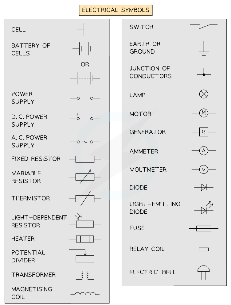
- Circuit diagrams use standard symbols to represent components.
- A cell or battery provides a source of potential difference; a battery is two or more cells.
- A switch turns the circuit on (closed) or off (open).
- A fixed resistor has a resistance that cannot change; a variable resistor can change its resistance, often used in dimmer switches and volume controls.
- A thermistor's resistance depends on temperature: as temperature increases, resistance decreases.
- An LDR (light-dependent resistor) has a resistance that depends on light intensity: as light intensity increases, resistance decreases.
- A diode allows current to flow in one direction only (forward bias); in reverse bias, it has very high resistance.
- An LED is a diode that emits light when current passes through it.
- A fuse is a safety device that melts and breaks the circuit if the current becomes too large.
- An ammeter measures current and is connected in series; a voltmeter measures potential difference and is connected in parallel.
Electrical symbols used in circuit diagrams
Charge and Current
- For charge to flow through a closed circuit, there must be a source of potential difference.
- Electric current is the rate of flow of electrical charge.
- In metals, the charge that flows is carried by electrons.
- The unit of charge is the coulomb (C); one coulomb is the charge passing a point when a current of 1 A flows for 1 second.
- Charge flow, current and time are related by the equation: Q = I t (charge = current × time).
- Current is measured in amperes (A) using an ammeter connected in series.
- In a single closed loop, the current has the same value at any point.
- Conventional current is the flow of positive charge from the positive terminal to the negative terminal; electrons flow in the opposite direction.
Potential Difference and Resistance
- Potential difference (p.d.) is the energy transferred per unit charge passing between two points; it is measured in volts (V).
- Potential difference is measured using a voltmeter connected in parallel with the component.
- Resistance is the opposition to current; it is measured in ohms (Ω).
- The current through a component depends on both its resistance and the potential difference across it.
- For a given potential difference, the greater the resistance, the smaller the current.
- The relationship between potential difference, current and resistance is given by: V = I R.
- An ohm is equivalent to one volt per ampere (1 V/A).
Required Practical: Investigating Resistance
- Investigate how the length of a wire at constant temperature affects its resistance.
- Independent variable: length of wire; dependent variable: resistance; control variables: potential difference of power supply and temperature of wire.
- Set up a circuit with a thin resistance wire, crocodile clips, ammeter, voltmeter and power supply.
- Measure current and potential difference for different lengths (e.g., 10 cm intervals up to 1 m).
- Calculate resistance using R = V / I for each length.
- Plot a graph of resistance against length; it should be a straight line through the origin, showing resistance is directly proportional to length.
- To reduce heating effects, switch off the circuit between readings and use small currents.
Resistors in Series and Parallel
- In series, the total resistance is the sum of the individual resistances: Rtotal = R1 + R2 + ...
- In series, the current is the same through each component, and the total potential difference is shared.
- In parallel, the total resistance is less than the sum of the individual resistances.
- In parallel, the potential difference across each branch is the same, and the current splits between branches.
- Adding more resistors in series increases total resistance; adding more in parallel decreases total resistance.
Ohmic Conductors and I–V Graphs
- Ohm's Law states that the current through a conductor is directly proportional to the potential difference across it, provided temperature is constant.
- Ohmic conductors have a constant resistance and their I–V graph is a straight line through the origin.
- Examples of ohmic conductors: fixed resistors, wires, heating elements.
- Non-ohmic conductors do not obey Ohm's Law; their resistance changes with current.
- Examples of non-ohmic conductors: filament lamps, diodes, thermistors, LDRs.
- For a filament lamp, as current increases, the filament temperature increases, causing resistance to increase; the I–V graph curves.
- For a diode, current flows in one direction only; the I–V graph shows a sharp increase in forward bias and zero current in reverse bias.
Thermistors and LDRs
- A thermistor is a temperature-dependent resistor; its resistance decreases as temperature increases.
- Thermistors are used in thermostats, ovens, refrigerators, fire alarms, digital thermometers and boilers.
- An LDR is a light-dependent resistor; its resistance decreases as light intensity increases.
- LDRs are used in automatic lights (e.g., street lights, garden lights), burglar alarms, and light meters.
- To investigate a thermistor, measure current and potential difference as temperature changes; calculate resistance using R = V / I.
- To investigate an LDR, measure current and potential difference as light intensity changes; calculate resistance using R = V / I.
- In both investigations, the ammeter is connected in series and the voltmeter in parallel with the component.
Required Practical: Investigating I–V Characteristics
- Aim: investigate the I–V characteristics of a fixed resistor, filament lamp and diode.
- Independent variable: potential difference; dependent variable: current; control variables: potential difference of power supply, same equipment.
- Set up a circuit with a variable resistor to change the potential difference across the component.
- Record current for a range of potential differences (both positive and negative).
- Plot a graph of current against potential difference for each component.
- The fixed resistor gives a straight line through the origin (ohmic); the filament lamp gives a curve; the diode gives a sharp increase in forward bias and zero in reverse bias.
- Switch off between readings to prevent heating, which would affect resistance.
슬라이드
연습 문제
무료 미리 보기 — 61개 중 8개 문제. 가입하면 전부 볼 수 있어요.
1.Which of the following is needed in a circuit for charge to flow?
Easy- AA source of resistance
- BA closed circuit loop
- CA source of potential difference
- DAn ammeter
2.Which of the following is the correct symbol for a battery?
Easy- ATwo parallel lines, one long and one short
- BTwo parallel lines of equal length
- CA circle with a cross inside
- DA zigzag line
3.Which instrument is used to measure potential difference?
Easy- AAmmeter
- BJoulemeter
- CNewtonmeter
- DVoltmeter
4.Which of the following diagrams shows the incorrect placement of a voltmeter?
Easy- AVoltmeter connected in parallel with a resistor
- BVoltmeter connected in series with a resistor
- CVoltmeter connected across a battery
- DVoltmeter connected across a lamp
5.Which of the following statements is not true about current?
Easy- ACurrent has the same value anywhere in a closed loop
- BCurrent is the rate of charge flow
- CCurrent is measured by a voltmeter
- DThe unit for current is the coulomb
6.The unit for charge is the coulomb. Which of the following is the correct equation for charge?
Easy- AQ = I / t
- BQ = t / I
- CQ = I t
- DQ = I + t
7.A resistor of 10 Ω has a current of 0.5 A through it. Calculate the potential difference across the resistor.
Medium- A0.05 V
- B5 V
- C20 V
- D0.5 V
8.Which of the following is the correct equation linking potential difference, current, and resistance?
Medium- AV = I R
- BV = I / R
- CV = I + R
- DV = I² R
기출 문제
이 주제의 기출 문제 연습이 곧 나와요.
곧 출시