
Communicating design ideas
Learn it by playing
Answer these questions to earn energy, then fish and explore. No account needed.
For educators: ready-to-use lesson slides, revision notes for Communicating design ideas (Design and Technology, Designing) — use them in your lesson, or run the topic as an interactive class activity your learners play as a live game.
Lesson notes
Why communicate?
- Select a communication method for the audience and decision. A client may need to compare appearance or understand use, while a maker needs sufficient dimensions, material specifications and assembly information. The commissioning client and end user may be different people.
- Combine methods when necessary: a sketch can explain a concept, a model can support feedback, and a working drawing can define manufacture. Clear presentation supports discussion but does not prove that an idea is feasible or meets the specification.
Sketching and rendering
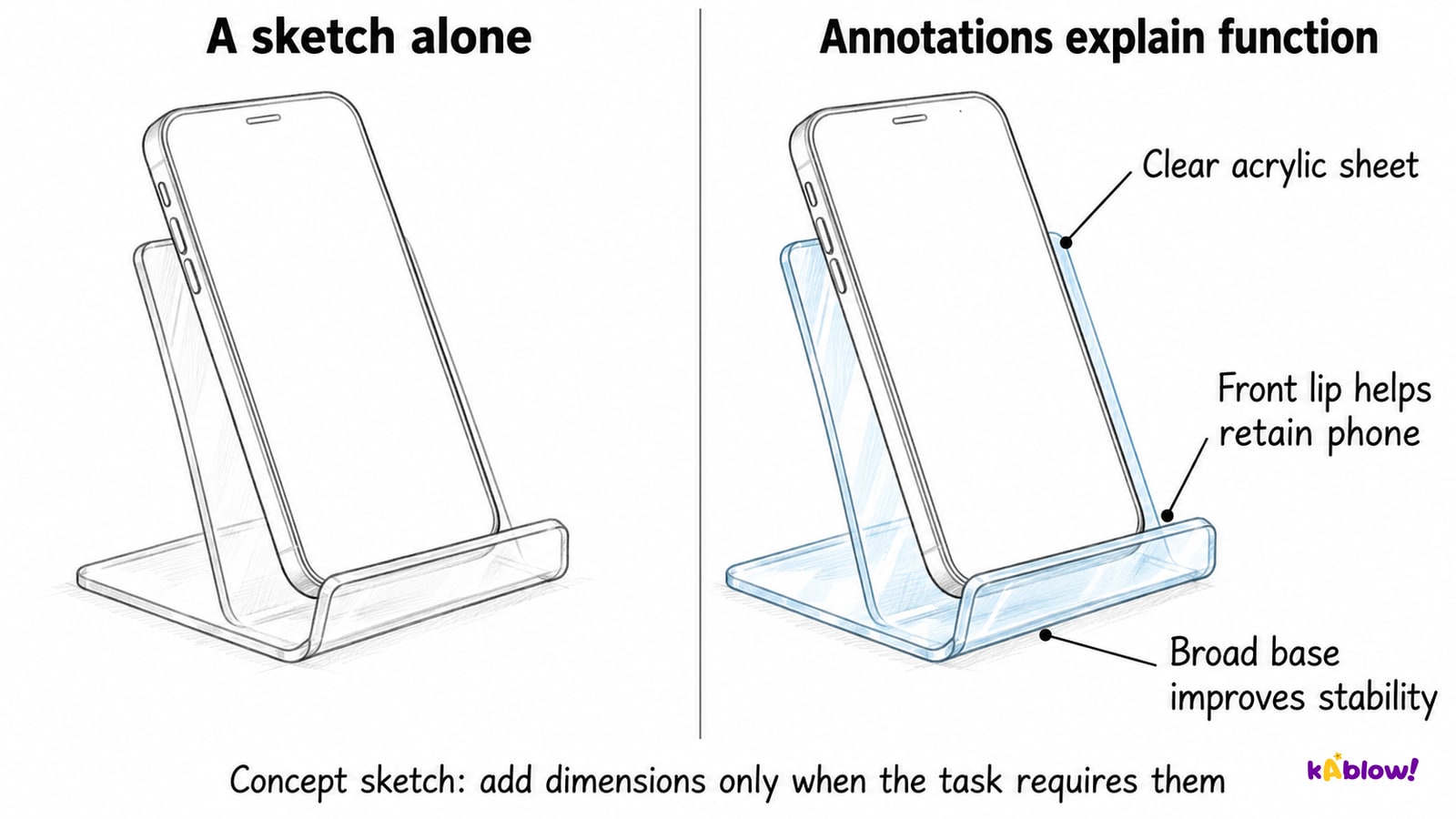
- Use thumbnail sketches to explore alternatives before developing selected ideas. Annotation connects short notes to relevant features, explaining materials, function, manufacture or user requirements. The original phone-stand concept shows how labelled features communicate more than an unannotated outline.
- Rendering adds tone, colour, texture or lighting to suggest appearance. It is useful for presentation, but a realistic image does not establish real sizes, material strength or manufacturability. Keep concept communication distinct from a fully specified production drawing.
Annotations connect features to function
3D drawings
- For conventional isometric drawing, the two receding axes are 30° to the horizontal and the third is vertical. The three positive axis directions are 120° apart. Use a consistent drawing scale along the axes; do not confuse this practical isometric-drawing convention with the foreshortening of a mathematically projected isometric view.
- An oblique drawing preserves the true shape of the front face and represents depth with receding parallel lines. The depth scale depends on the chosen convention. Perspective gives a visual impression of depth using appropriate vanishing points; true lengths generally cannot be taken directly from its apparent edges.
- An exploded view separates components while retaining their assembly relationships. It can use an isometric or other pictorial projection, so it is an arrangement rather than a separate projection system. Additional fixings, detail views or notes may be needed to communicate an actual assembly.
Cabinet oblique view
2D working drawings
- Orthographic projection shows selected perpendicular views. For the illustrated 60 × 40 × 20 mm cuboid, plan shows 60 × 40, front 60 × 20 and side 40 × 20 mm. All illustrated rectangles share a scale, but their separate panel arrangement is not a first- or third-angle projection sheet.
- Third-angle places the top view above the front and the right-side view to its right. First-angle uses different positions. Identify the specified convention and keep it consistent; do not infer a universal arrangement from an unlabelled set of views.
- Short dashed lines conventionally represent hidden edges; thin chain lines commonly indicate centres or axes. Dimensions state intended real sizes, with units and tolerances where required. Use sufficient views, details or sections to remove ambiguity instead of assuming three views always show every feature.
- Scale compares drawing and real lengths in matching units. At 1:2 a real 80 mm edge is drawn 40 mm; at 1:5 a drawn 18 mm edge represents 90 mm. Written dimensions specify real sizes. Resizing a print or screen image invalidates measurements taken from its nominal scale.
Compare cuboid views
CAD and digital
- CAD means computer-aided design, covering appropriate 2D and 3D tools. It can support precise geometry, efficient editing and reuse, but dimensions, constraints, units and revisions require checking. A digital file can contain incorrect or incomplete information.
- A virtual model can help inspect form and fit. Simulation needs suitable material data, loads, constraints and assumptions, and physical or user testing may still be required. CAM needs compatible manufacturing data and machine setup; sending a file does not automatically make a valid part.
CAD supports decisions; check the inputs
Models
- Card, foam or clay models can test aspects of form, size or interaction quickly. A model’s material and fidelity limit what can be inferred: a card model may reveal access problems but cannot establish the load capacity of a final metal product. 3D prints also have process- and material-specific limitations.
- Mood boards communicate a style direction using relevant visual references. Ask for specific feedback and record the resulting design decision, rather than treating a favourable appearance comment as evidence that all technical requirements are met.
Templates and manufacturing documents
- A template repeats a profile or feature location; check its accuracy and condition. A cutting list records relevant component materials, quantities and cut sizes. A bill of materials identifies the required materials and parts, often with quantities and specification references.
- A manufacturing flow chart communicates sequence and relevant decision or quality checks. Keep the drawing, lists and model on the same revision so that a change in one document does not leave conflicting manufacturing instructions.
Different documents answer different questions
Slides
Sign up free to view the lesson slides
Step through every slide for this topic — plus flashcards and revision notes — with a free account.
Practice questions
Free preview — 8 of 35 questions. Sign up to see them all.
1.What is a thumbnail sketch?
Easy- Aa small quick sketch of an idea
- Ba final drawing
- Ca prototype
- Da model
2.What is rendering?
Easy- Acutting metal
- Bbuilding a model
- Cwriting a brief
- Dadding tone, colour and texture to a drawing
3.In a conventional isometric drawing, what angle do the receding axes make with the horizontal?
Easy- A90°
- B60°
- C30°
- D45°
4.What does CAD stand for?
Easy- Acut and draw
- Bcomputer-aided design
- Ccomputer assembled drawing
- Dcontrol and draw
5.What is an exploded view?
Easy- Aparts drawn separated to show assembly
- Ba perspective drawing
- Ca sketch
- Da diagram
6.What does a dashed line show on an orthographic drawing?
Easy- Athe outline
- Bthe centre
- Ca dimension
- Dhidden detail
7.What does a chain line (long dash, short dash) often show?
Easy- Athe outline
- Ba dimension
- Ca centre line
- Dhidden detail
8.What is scale on a drawing?
Easy- Athe cost
- Bthe ratio of drawing size to real size
- Cthe weight
- Dthe colour
Unlock all 35 questions & more
Create a free account to see every question, the slides, flashcards and revision notes for this topic.
Past papers
Past-paper practice for this topic is coming soon.
Coming soon