Electric Circuits & Electrical Safety
邊玩邊學
回答這些題目賺取能量,接著就能釣魚、探索。不需要帳號。
給教育者: 為 Electric Circuits & Electrical Safety(Physics、CIE)準備好可直接使用的課程投影片, 複習筆記, 圖表——用於你的課程,或把這個主題當成互動班級活動,讓學習者以即時遊戲的方式進行。
課程筆記
Circuit Diagrams & Circuit Components
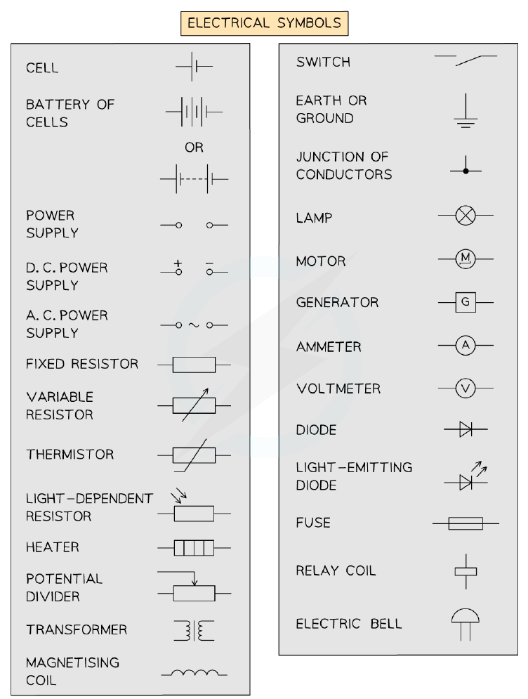
- Circuit symbols represent components like cells, resistors, meters, switches, and functional devices.
- Ammeters are connected in series; voltmeters are connected in parallel.
- Thermistors: resistance decreases as temperature increases.
- LDRs: resistance decreases as light intensity increases.
- Diodes allow current in one direction only (arrow direction); LEDs also emit light.
- Fuses protect against current surges; they melt and break the circuit if current is too high.
Electrical symbols used in circuit diagrams
Current in Series Circuits
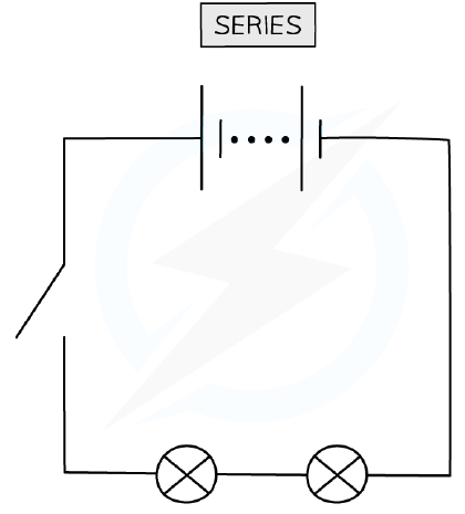
- A series circuit has a single complete loop.
- Current is the same at every point in a series circuit.
- Current depends on: voltage of the power source and total resistance of components.
- Increasing voltage increases current; increasing number of components decreases current (due to higher resistance).
A simple series circuit
Current in Parallel Circuits
- A parallel circuit has multiple loops (branches).
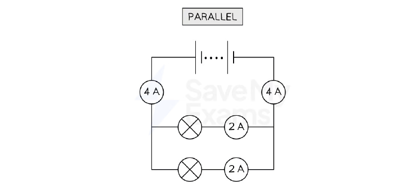
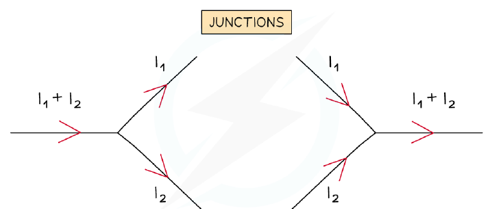
- Current splits at junctions; total current entering a junction equals total current leaving (charge conservation).
- Current in each branch depends on the resistance of that branch; equal only if resistances are equal.
- Lighting circuits are wired in parallel so each bulb has the same brightness and bulbs can be switched independently.
Calculation of current splitting at a junction in a parallel circuit
EMF & Potential Difference
- Cells in series: total e.m.f. = sum of individual e.m.f.s.
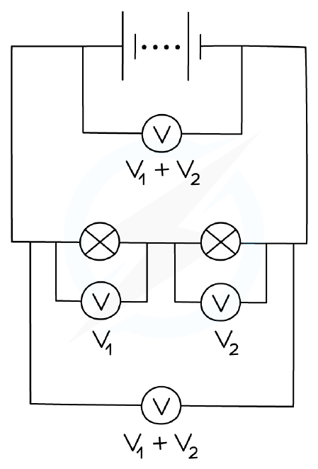
- In a series circuit, sum of p.d.s across components = total e.m.f. of the power supply.
- In a parallel circuit, p.d. across each branch = e.m.f. of the power supply (same for all branches).
Example calculation for potential difference in series
Combined Resistance
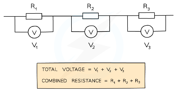
- Resistors in series: total resistance = sum of individual resistances.
- Resistors in parallel: combined resistance is less than the smallest individual resistance.
- For two resistors in parallel: 1/R = 1/R₁ + 1/R₂.
- Two equal resistors in parallel give half the resistance of one.
Combined resistance of resistors in series
Potential Dividers (Extended Tier)
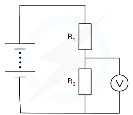
- A potential divider uses two resistors in series to split the e.m.f. into smaller voltages.
- The p.d. across each resistor is proportional to its resistance: R₁/R₂ = V₁/V₂.
- If one resistor is variable, the output voltage can be adjusted.
- The sum of the p.d.s across the two resistors equals the total e.m.f. (V₁ + V₂ = Vin).
Potential divider diagram
Electrical Safety
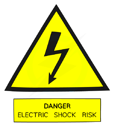
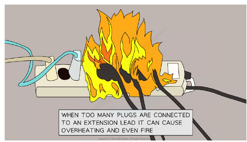
- Common hazards: damaged insulation, overheating cables, damp conditions, overloading sockets.
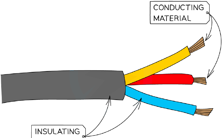
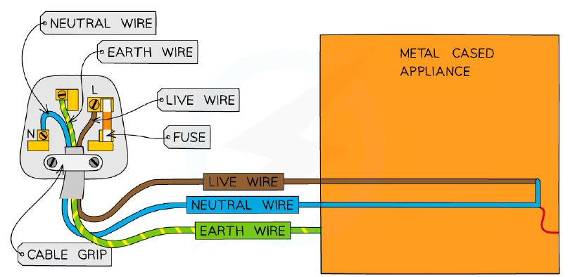
- Mains circuit wires: live (brown), neutral (blue), earth (green/yellow).
- The earth wire provides a low-resistance path to ground; if the live wire touches the metal case, a large current flows and blows the fuse.
- Double insulation (two layers of insulation, non-metallic case) means no earth wire is needed.
- Fuses (3 A, 5 A, 13 A) melt and break the circuit if current exceeds their rating; choose the smallest rating above the normal current.
- Circuit breakers (trip switches) automatically switch off when current is too high; they can be reset.
Cross-section of a mains cable showing conducting and insulating materials
投影片
練習題
免費預覽——50 題中的 8 題。註冊即可查看全部。
1.Which circuit symbol represents a fuse?
Easy- AA resistor symbol with a zigzag line
- BA rectangle with a line through it
- CA circle with a cross inside
- DA triangle pointing to a line
2.What is the purpose of a fuse in a mains electrical circuit?
Easy- ATo reduce the current flowing through the appliance
- BTo increase the resistance of the circuit so the appliance works safely
- CTo break the circuit if the current becomes too large
- DTo prevent the voltage from becoming too high
3.Which of the following is the correct circuit symbol for a thermistor?
Easy- AA resistor with a diagonal arrow through it
- BA resistor with a curved line through it
- CA circle with a cross inside
- DA rectangle with a line through it
4.In a series circuit with a battery and two resistors, the current is 0.5 A. If a third resistor is added in series, what happens to the current?
Easy- AIt increases
- BIt decreases
- CIt stays the same
- DIt becomes zero
5.Two resistors of 4 Ω and 6 Ω are connected in parallel. What is the total resistance?
Medium- A10 Ω
- B2.4 Ω
- C5 Ω
- D24 Ω
6.In a potential divider circuit, resistor R1 = 10 kΩ and R2 = 20 kΩ are in series across a 9 V supply. What is the voltage across R2?
Medium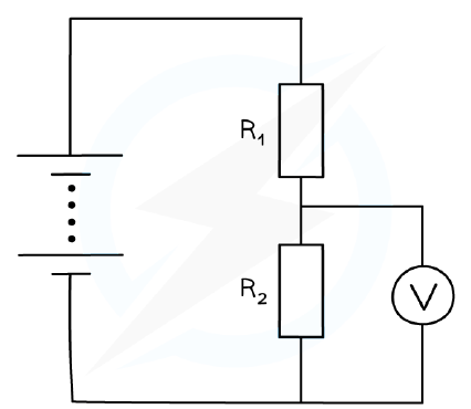
- A3 V
- B6 V
- C9 V
- D4.5 V
7.What colour is the insulation on the earth wire in a UK mains plug?
Easy- ABrown
- BBlue
- CGreen and yellow stripes
- DRed
8.A double-insulated appliance does not require an earth wire because:
Easy- AIt has a metal case that is earthed
- BIt has two layers of insulation around live parts
- CIt uses a lower voltage
- DIt has a built-in fuse
歷屆試題
這個主題的歷屆試題練習即將推出。
即將推出